R
Spartan-II FPGA Family: Functional Description
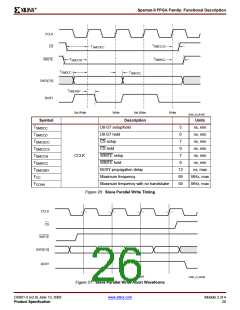
If CCLK is slower than FCCNH, the FPGA will never assert
BUSY. In this case, the above handshake is unnecessary,
and data can simply be entered into the FPGA every CCLK
cycle.
interface does not expect any data and ignores all CCLK
transitions. However, to avoid aborting configuration,
WRITE must continue to be asserted while CS is asserted.
Abort
To abort configuration during a write sequence, de-assert
WRITE while holding CS Low. The abort operation is
initiated at the rising edge of CCLK, as shown in Figure 21,
page 26. The device will remain BUSY until the aborted
operation is complete. After aborting configuration, data is
assumed to be unaligned to word boundaries and the FPGA
requires a new synchronization word prior to accepting any
new packets.
After INIT
Goes High
User Drives
WRITE and CS
Low
Boundary-Scan Mode
In the boundary-scan mode, no nondedicated pins are
required, configuration being done entirely through the
IEEE 1149.1 Test Access Port.
Load One
Configuration
Byte on Next
CCLK Rising Edge
Configuration through the TAP uses the special CFG_IN
instruction. This instruction allows data input on TDI to be
converted into data packets for the internal configuration
bus.
FPGA
Yes
The following steps are required to configure the FPGA
through the boundary-scan port.
Driving BUSY
High?
1. Load the CFG_IN instruction into the boundary-scan
instruction register (IR)
No
2. Enter the Shift-DR (SDR) state
3. Shift a standard configuration bitstream into TDI
4. Return to Run-Test-Idle (RTI)
End of
No
Configuration
Data File?
5. Load the JSTART instruction into IR
6. Enter the SDR state
Yes
User Drives
WRITE and CS
High
7. Clock TCK through the sequence (the length is
programmable)
8. Return to RTI
Configuration and readback via the TAP is always available.
The boundary-scan mode simply locks out the other modes.
The boundary-scan mode is selected by a <10x> on the
mode pins (M0, M1, M2).
To CRC Check
DS001_19_032300
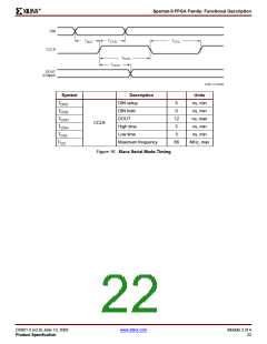
Figure 19: Loading Configuration Data for the Slave
Parallel Mode
Readback
The configuration data stored in the Spartan-II FPGA
configuration memory can be readback for verification.
Along with the configuration data it is possible to readback
the contents of all flip-flops/latches, LUT RAMs, and block
RAMs. This capability is used for real-time debugging.
A configuration packet does not have to be written in one
continuous stretch, rather it can be split into many write
sequences. Each sequence would involve assertion of CS.
In applications where multiple clock cycles may be required
to access the configuration data before each byte can be
loaded into the Slave Parallel interface, a new byte of data
may not be ready for each consecutive CCLK edge. In such
a case the CS signal may be de-asserted until the next byte
is valid on D0-D7. While CS is High, the Slave Parallel
For more detailed information see XAPP176, Spartan-II
FPGA Family Configuration and Readback.
DS001-2 (v2.8) June 13, 2008
Product Specification
www.xilinx.com
Module 2 of 4
25

 XILINX [ XILINX, INC ]