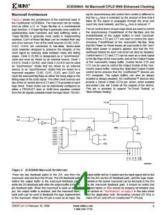
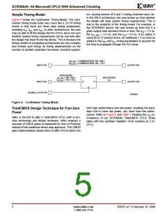
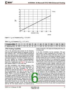
R
XCR3064A: 64 Macrocell CPLD With Enhanced Clocking
pins when fabricating a PC board. Allowing unused inputs
and I/O pins to float can cause the voltage to be in the lin-
3V, In-System Programming (ISP)
ISP is the ability to reconfigure the logic and functionality of
a device, printed circuit board, or complete electronic sys-
tem before, during, and after its manufacture and shipment
to the end customer. ISP provides substantial benefits in
each of the following areas:
ear region of the CMOS input structures, which can
increase the power consumption of the device. The
XCR3064A CPLDs have programmable on-chip pull-down
resistors on each I/O pin. These pull-downs are automati-
cally activated by the fitter software for all unused I/O pins.
Note that an I/O macrocell used as buried logic that does
not have the I/O pin used for input is considered to be
unused, and the pull-down resistors will be turned on. We
recommend that any unused I/O pins on the XCR3064A
device be left unconnected.
•
•
Design
-
-
-
-
Faster time-to-market
Debug partitioning and simplified prototyping
Printed circuit board reconfiguration during debug
Better device and board level testing
There are no on-chip pull-down structures associated with
the dedicated input pins. Xilinx recommends that any
unused dedicated inputs be terminated with external 10kΩ
pull-up resistors. These pins can be directly connected to
Manufacturing
-
-
-
Multi-Functional hardware
Reconfigurability for test
Eliminates handling of "fine lead-pitch" components
for programming
V
or GND, but using the external pull-up resistors main-
CC
tains maximum design flexibility should one of the unused
dedicated inputs be needed due to future design changes.
-
-
Reduced Inventory and manufacturing costs
Improved quality and reliability
When using the JTAG/ISP functions, it is also recom-
mended that 10kΩ pull-up resistors be used on each of the
pins associated with the four mandatory JTAG signals. Let-
ting these signals float can cause the voltage on TMS to
come close to ground, which could cause the device to
enter JTAG/ISP mode at unspecified times. See the appli-
cation notes JTAG and ISP Overview for Xilinx XPLA1 and
XPLA2 CPLDs and Terminating Unused I/O Pins in Xilinx
XPLA1 and XPLA2 CoolRunner CPLDs for more informa-
tion.
•
Field Support
-
-
Easy remote upgrades and repair
Support for field configuration, reconfiguration, and
customization
The Xilinx XCR3064A allows for 3.3V, in-system program-
ming/reprogramming of its EEPROM cells via its JTAG
interface. An on-chip charge pump eliminates the need for
externally-provided superVoltages, so that the XCR3064A
may be easily programmed on the circuit board using only
the 3V supply required by the device for normal operation.
A set of low-level ISP basic commands implemented in the
XCR3064A enable this feature. The ISP commands imple-
mented in the Xilinx XCR3064A are specified in Table 5
Please note that an ENABLE command must precede all
ISP commands unless an ENABLE command has already
been given for a preceding ISP command.
JTAG and ISP Interfacing
A
number of industry-established methods exist for
JTAG/ISP interfacing with CPLDs and other integrated cir-
cuits. The XCR3064A supports the following methods:
•
•
•
•
•
•
PC parallel port
Workstation or PC serial port
Embedded processor
Automated test equipment
Third party programmers
High-End ISP Tools
Terminations
The CoolRunner XCR3064A CPLDs are TotalCMOS
devices. As with other CMOS devices, it is important to
consider how to properly terminate unused inputs and I/O
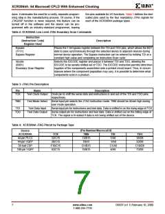
Table 5: Low Level ISP Commands
Instruction
Instruction Code
(Register Used)
Description
Enable
(ISP Shift Register)
1001
1010
1011
1100
Enables the Erase, Program, and Verify commands.
Erases the entire EEPROM array.
Erase
(ISP Shift Register)
Program
(ISP Shift Register)
Programs the data in the ISP Shift Register into the addressed EEPROM row.
Verify
(ISP Shift Register)
Transfers the data from the addressed row to the ISP Shift Register. The data
can then be shifted out and compared with the JEDEC file. The outputs during
this operation can be defined by the user.
DS037 (v1.1) February 10, 2000
www.xilinx.com
8
1-800-255-7778

 XILINX [ XILINX, INC ]