R
XCR3064A: 64 Macrocell CPLD With Enhanced Clocking
ing for asynchronous and control term clocks is different in
Macrocell Architecture
that the t
time is extended by the amount of time that it
CO
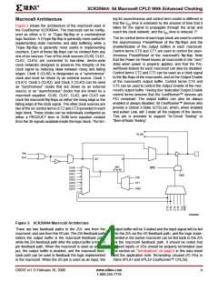
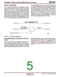
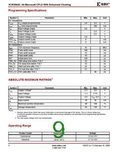
Figure 3 shows the architecture of the macrocell used in
the CoolRunner XCR3064A. The macrocell can be config-
ured as either a D- or T-type flip-flop or a combinatorial
logic function. A D-type flip-flop is generally more useful for
implementing state machines and data buffering while a
T-type flip-flop is generally more useful in implementing
counters. Each of these flip-flops can be clocked from any
one of six sources. Four of the clock sources (CLK0, CLK1,
CLK2, CLK3) are connected to low-skew, device-wide
clock networks designed to preserve the integrity of the
clock signal by reducing skew between rising and falling
edges. Clock 0 (CLK0) is designated as a "synchronous"
clock and must be driven by an external source. Clock 1
(CLK1), Clock 2 (CLK2), and Clock 3 (CLK3) can be used
as "synchronous" clocks that are driven by an external
source, or as "asynchronous" clocks that are driven by a
macrocell equation. CLK0, CLK1, CLK2, and CLK3 can
clock the macrocell flip-flops on either the rising edge or the
falling edge of the clock signal. The other clock sources are
two of the six control terms (CT2 and CT3) provided in each
logic block. These clocks can be individually configured as
either a PRODUCT term or SUM term equation created
from the 36 signals available inside the logic block. The tim-
takes for the signal to propagate through the array and
reach the clock network, and the t time is reduced. P
SU
The six control terms of each logic block are used to control
the asynchronous Preset/Reset of the flip-flops and the
enable/disable of the output buffers in each macrocell.
Control terms CT0 and CT1 are used to control the asyn-
chronous Preset/Reset of the macrocell’s flip-flop. Note
that the Power-on Reset leaves all macrocells in the "zero"
state when power is properly applied, and that the Pre-
set/Reset feature for each macrocell can also be disabled.
Control terms CT2 and CT3 can be used as a clock signal
to the flip-flops of the macrocells, and as the Output Enable
of the macrocell’s output buffer. Control terms CT4 and
CT5 can be used to control the Output Enable of the mac-
rocell’s output buffer. Having four dedicated Output Enable
control terms ensures that the CoolRunner™ devices are
PCI compliant. The output buffers can also be always
enabled or always disabled. All CoolRunner™ devices also
provide a Global 3-State (GTS) pin, which, when enabled
and pulled Low, will 3-state all the outputs of the device.
This pin is provided to support "In-Circuit Testing" or
"Bed-of-Nails Testing".
TO ZIA
PAL
PLA
D/T
Q
INIT
(P or R)
CLK0
CLK0
CLK1
CLK1
CLK2
CLK2
CLK3
CLK3
GTS
GND
CT0
CT1
GND
SP00558
Figure 3: XCR3064A Macrocell Architecture
There are two feedback paths to the ZIA: one from the
macrocell, and one from the I/O pin. The ZIA feedback path
before the output buffer is the macrocell feedback path,
while the ZIA feedback path after the output buffer is the I/O
pin feedback path. When the macrocell is used as an out-
put, the output buffer is enabled, and the macrocell feed-
back path can be used to feedback the logic implemented
in the macrocell. When the I/O pin is used as an input, the
output buffer will be 3-stated and the input signal will be fed
into the ZIA via the I/O feedback path, and the logic imple-
mented in the buried macrocell can be fed back to the ZIA
via the macrocell feedback path. It should be noted that
unused inputs or I/Os should be properly terminated (see
the section on “Terminations” on page 8 in this data sheet
and the application note Terminating Unused I/O Pins in
Xilinx XPLA1 and XPLA2 CoolRunner™ CPLDs).
DS037 (v1.1) February 10, 2000
www.xilinx.com
1-800-255-7778
4

 XILINX [ XILINX, INC ]