Spartan-3E FPGA Family: Functional Description
Bitstream Generator (BitGen) Options
For additional information, refer to the “Configuration
Bitstream Generator (BitGen) Settings” chapter in UG332.
values are specified when creating the bitstream image with
the Bitstream Generator (BitGen) software.
Various Spartan-3E FPGA functions are controlled by
specific bits in the configuration bitstream image. These
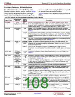
Table 69 provides a list of all BitGen options for Spartan-3E
FPGAs.
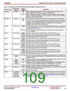
Table 69: Spartan-3E FPGA Bitstream Generator (BitGen) Options
Pins/Function
Affected
Values
(default)
Option Name
Description
ConfigRate
CCLK,
Configuration
1, 3, 6,
Sets the approximate frequency, in MHz, of the internal oscillator using for Master
12, 25, 50 Serial, SPI, and BPI configuration modes. The internal oscillator powers up at its lowest
frequency, and the new setting is loaded as part of the configuration bitstream. The
software default value is 1 (~1.5 MHz) starting with ISE 8.1, Service Pack 1.
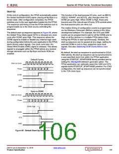
StartupClk
Configuration,
Startup
Cclk
Default. The CCLK signal (internally or externally generated) controls the startup
sequence when the FPGA transitions from configuration mode to the user mode. See
Start-Up.
UserClk A clock signal from within the FPGA application controls the startup sequence when the
FPGA transitions from configuration mode to the user mode. See Start-Up. The FPGA
application supplies the user clock on the CLK pin on the STARTUP_SPARTAN3E
primitive.
Jtag
The JTAG TCK input controls the startup sequence when the FPGA transitions from the
configuration mode to the user mode. See Start-Up.
UnusedPin
Unused I/O
Pins
Pulldown Default. All unused I/O pins and input-only pins have a pull-down resistor to GND.
Pullup
All unused I/O pins and input-only pins have a pull-up resistor to the VCCO_# supply
for its associated I/O bank.
Pullnone All unused I/O pins and input-only pins are left floating (Hi-Z, high-impedance,
three-state). Use external pull-up or pull-down resistors or logic to apply a valid signal
level.
DONE_cycle
GWE_cycle
DONE pin,
Configuration
Startup
1, 2, 3, 4, Selects the Configuration Startup phase that activates the FPGA’s DONE pin. See
5, 6
Start-Up.
All flip-flops,
LUTRAMs,and
SRL16 shift
registers, Block
RAM,
Configuration
Startup
1, 2, 3, 4, Selects the Configuration Startup phase that asserts the internal write-enable signal to
5, 6
all flip-flops, LUT RAMs and shift registers (SRL16). It also enables block RAM read and
write operations. See Start-Up.
Done
Waits for the DONE pin input to go High before asserting the internal write-enable signal
to all flip-flops, LUT RAMs and shift registers (SRL16). Block RAM read and write
operations are enabled at this time.
Keep
Retains the current GWE_cycle setting for partial reconfiguration applications.
GTS_cycle
All I/O pins,
Configuration
1, 2, 3, 4, Selects the Configuration Startup phase that releases the internal three-state control,
5, 6
holding all I/O buffers in high-impedance (Hi-Z). Output buffers actively drive, if so
configured, after this point. See Start-Up.
Done
Waits for the DONE pin input to go High before releasing the internal three-state control,
holding all I/O buffers in high-impedance (Hi-Z). Output buffers actively drive, if so
configured, after this point.
Keep
Retains the current GTS_cycle setting for partial reconfiguration applications.
LCK_cycle
DonePin
DCMs,
Configuration
Startup
NoWait The FPGA does not wait for selected DCMs to lock before completing configuration.
0, 1, 2, 3, If one or more DCMs in the design have the STARTUP_WAIT attribute set to TRUE, the
4, 5, 6
FPGA waits for such DCMs to acquire their respective input clock and assert their
LOCKED output. This setting selects the Configuration Startup phase where the FPGA
waits for the DCMs to lock.
DONE pin
Pullup
Internally connects a pull-up resistor between DONE pin and VCCAUX. An external
330 Ω pull-up resistor to VCCAUX is still recommended.
Pullnone No internal pull-up resistor on DONE pin. An external 330 Ω pull-up resistor to VCCAUX
is required.
DS312 (v4.2) December 14, 2018
www.xilinx.com
Product Specification
108

 XILINX [ XILINX, INC ]