Philips Semiconductors
Preliminary specification
320 macrocell SRAM CPLD
PZ3320C/PZ3320N
the internal configuration memory. The configuration loading process
is complete when the internal length count equals the loaded length
count in the length count field, and the required end of configuration
frame is written.
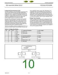
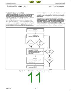
PZ3320 STATES OF OPERATION
Prior to becoming operational, the PZ3320 goes through a sequence
of states, including initialization, configuration, and start-up. This
section discusses these three states. In the master configuration
modes, the PZ3320 is the source of configuration clock (cclk). In this
mode, the Initialization state is extended to ensure that, in
daisy-chain operation, all daisy-chained slave devices are ready.
All configuration I/Os used as inputs operate with TTL-level input
thresholds during configuration. All I/Os that are not used during the
configuration process are 3-Stated with internal pull-downs. During
configuration, registers are reset. The combinatorial logic begins to
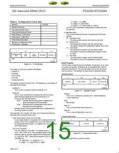
function as the PZ3320 is configured. Figure 8 shows the flow
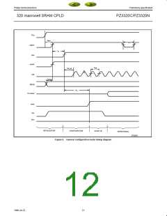
between the initialization, configuration, and start-up states. Figure 9
gives the general timing information for configuring the device.
When configuration is initiated, a counter in the PZ3320 is set to 0
and begins to count configuration clock cycles applied to the PZ3320.
As each configuration data frame is supplied to the PZ3320, it is
internally assembled into data words. Each data word is loaded into
POWER-UP
POWER-ON TIME DELAY
–
–
INITIALIZATION
initn LOW, hdc HIGH, ldcn LOW
resetn,
initn,
OR
prgmn
LOW
BIT ERROR
YES
YES
NO
NO
CONFIGURATION
M[3:0] MODE IS SELECTED
–
–
–
–
resetn
OR
prgmn
CONFIGURATION DATA FRAME WRITTEN
initn HIGH, hdc HIGH, ldcn LOW
dout ACTIVE
LOW
START-UP
prgmn
LOW
–
–
–
ALL MACROCELL FF’S ARE RESET
RELEASE INTERNAL RESET
done GOES HIGH
OPERATION
–
I/O BECOMES ACTIVE
SP00622
Figure 8. Flow chart of initialization, configuration, and operating states
11
1998 Jul 22

 XILINX [ XILINX, INC ]