Philips Semiconductors
Preliminary specification
320 macrocell SRAM CPLD
PZ3320C/PZ3320N
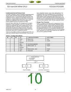
basic configuration methods: master, slave, and peripheral. The
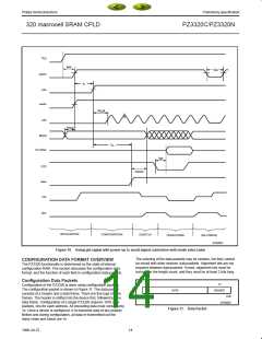
configuration data can be transmitted to the PZ3320 serially or in
parallel bytes. As a master, the PZ3320 generates the clock and
control signals to strobe configuration data into the PZ3320. As a
slave device, a clock is generated externally, and provided into the
PZ3320’s cclk pin. In the peripheral mode, the PZ3320 interfaces as
a microprocessor peripheral. Table 3 lists the configuration modes.
CONFIGURATION INTRODUCTION
The Philips CoolRunner series are available in technologies which
use non-volatile (EEPROM-based) and volatile (SRAM based)
configuration memory. The functionality of the XPLA2 family of the
CoolRunner series is defined by on-chip SRAM. The devices are
configured in a manner similar to that of most FPGAs. This section
describes the configuration of the PZ3320, and applies to all
similarly configured devices to be produced by Philips.
Design Flow Overview
Either the Philips or Minc fitter, XPLA Designer and PL-Designer,
respectively, is used to generate a JEDEC file. The JEDEC file
contains the configuration data, which is loaded into the PZ3320
configuration memory to control the PZ3320 functionality. This is
done at power-up and/or with configure command. This section
provides some of the trade-offs in selecting a configuration mode,
and provides debug hints for configuration problems.
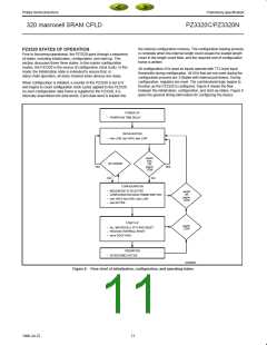
Figure 7 is a diagram of the steps used in configuring the PZ3320.
The development system is used to generate configuration data in
the JEDEC file. Using the <design>.jed file, there are two general
methods of configuring the PZ3320. The utility download can load
the configuration data from a PC or workstation hard disk into the
PZ3320. This is one of the methods used on the PZ3320 evaluation
board. Alternately, the PZ3320 can be loaded from non-volatile ICs
such as serial or parallel EEPROMs.
There are several different methods of configuring the PZ3320. The
mode used is selected using the mode select pins. There are three
Table 3. Configuration Modes
M2
M1
M0
cclk
CONFIGURATION MODE
DATA FORMAT
Serial
Output
Input
Master serial
Slave parallel
Parallel
Reserved
Input
Synchronous peripheral
Master parallel – up
Parallel
Parallel
Output
Reserved
Output
Input
Master parallel – down
Slave serial
Parallel
Serial
DESIGN COMPILATION
–
–
XPLA DESIGNER
PL-DESIGNER
jed
gen_mcs
download
PROM PROGRAMMER
SLAVE SERIAL CONFIGURATION
SP00616
Figure 7. Design flow
10
1998 Jul 22

 XILINX [ XILINX, INC ]