Spartan-6 FPGA Data Sheet: DC and Switching Characteristics
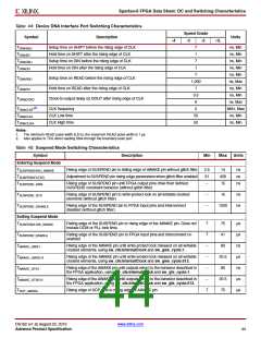
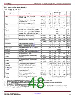
Table 44: Device DNA Interface Port Switching Characteristics
Speed Grade
-3 -2
Symbol
Description
Units
-4
-1L
TDNASSU
Setup time on SHIFT before the rising edge of CLK
Hold time on SHIFT after the rising edge of CLK
Setup time on DIN before the rising edge of CLK
Hold time on DIN after the rising edge of CLK
7
1
ns, Min
ns, Min
ns, Min
ns, Min
ns, Min
ns, Max
ns, Min
ns, Min
ns, Max
MHz, Max
ns, Min
ns, Min
TDNASH
TDNADSU
TDNADH
7
1
7
TDNARSU
TDNARH
Setup time on READ before the rising edge of CLK
Hold time on READ after the rising edge of CLK
Clock-to-output delay on DOUT after rising edge of CLK
1,000
1
0.5
6
TDNADCKO
(2)
TDNACLKF
TDNACLKL
TDNACLKH
CLK frequency
CLK Low time
CLK High time
2
50
50
Notes:
1. The minimum READ pulse width is 8 ns, the maximum READ pulse width is 1 µs.
2. Also applies to TCK when reading DNA through the boundary-scan port.
Table 45: Suspend Mode Switching Characteristics
Symbol
Entering Suspend Mode
TSUSPENDHIGH_AWAKE
TSUSPENDFILTER
Description
Min
Max
Units
Rising edge of SUSPEND pin to falling edge of AWAKE pin without glitch filter
Adjustment to SUSPEND pin rising edge parameters when glitch filter enabled
2.5
31
–
14
430
15
ns
ns
ns
TSUSPEND_GWE
Rising edge of SUSPEND pin until FPGA output pins drive their defined
SUSPEND constraint behavior (without glitch filter)
TSUSPEND_GTS
Rising edge of SUSPEND pin to write-protect lock on all writable clocked
elements (without glitch filter)
–
–
15
ns
ns
TSUSPEND_DISABLE
Rising edge of the SUSPEND pin to FPGA input pins and interconnect
disabled (without glitch filter)
1500
Exiting Suspend Mode
TSUSPENDLOW_AWAKE
Falling edge of the SUSPEND pin to rising edge of the AWAKE pin. Does not
include DCM or PLL lock time.
7
7
–
–
–
–
7
75
41
µs
µs
ns
µs
ns
µs
µs
TSUSPEND_ENABLE
TAWAKE_GWE1
TAWAKE_GWE512
TAWAKE_GTS1
Falling edge of the SUSPEND pin to FPGA input pins and interconnect re-
enabled
Rising edge of the AWAKE pin until write-protect lock released on all writable
clocked elements, using sw_clk:InternalClock and sw_gwe_cycle:1.
80
Rising edge of the AWAKE pin until write-protect lock released on all writable
clocked elements, using sw_clk:InternalClock and sw_gwe_cycle:512.
20.5
80
Rising edge of the AWAKE pin until outputs return to the behavior described in
the FPGA application, using sw_clk:InternalClock and sw_gts_cycle:1.
TAWAKE_GTS512
TSCP_AWAKE
Rising edge of the AWAKE pin until outputs return to the behavior described in
the FPGA application, using sw_clk:InternalClock and sw_gts_cycle:512.
20.5
75
Rising edge of SCP pins to rising edge of AWAKE pin
DS162 (v1.9) August 23, 2010
www.xilinx.com
Advance Product Specification
44

 XILINX [ XILINX, INC ]