X1241 – Preliminary Information
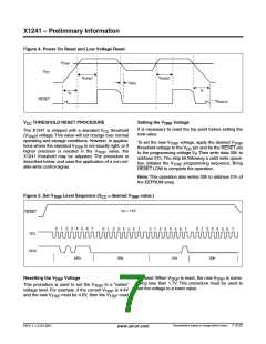
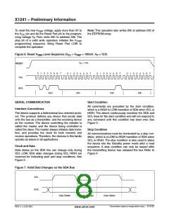
To reset the new V
voltage, apply more than 3V to
Note: This operation also writes 00h to address 03h of
TRIP
the V
pin and tie the Reset Pad pin to the program-
the EEPROM array.
CC
ming voltage V . Then write 00h to address 03h. The
P
stop bit of a valid write operation initiates the V
TRIP
programming sequence. Bring Reset Pad LOW to
complete the operation.
Figure 6. Reset V
Level Sequence (V > V
+ 100mV, V = 15V)
TRIP
CC
TRIP
P
V
= 15V
P
RESET
0
1
2
3
4
5 6 7
0
1
2
3
4
5
6
7
0
1
2
3
4
5
6
7
0
1
2
3
4
5 6 7
SCL
SDA
AEh
00h
03h
00h
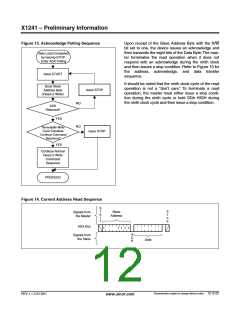
SERIAL COMMUNICATION
Interface Conventions
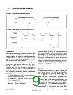
Start Condition
All commands are preceded by the start condition,
which is a HIGH to LOW transition of SDA when SCL is
HIGH. The device continuously monitors the SDA and
SCL lines for the start condition and will not respond to
any command until this condition has been met. See
Figure 3.
The device supports a bidirectional bus oriented proto-
col. The protocol defines any device that sends data
onto the bus as a transmitter, and the receiving device
as the receiver. The device controlling the transfer is
called the master and the device being controlled is
called the slave.The master always initiates data trans-
fers, and provides the clock for both transmit and
receive operations. Therefore, the devices in this family
operate as slaves in all applications.
Stop Condition
All communications must be terminated by a stop con-
dition, which is a LOW to HIGH transition of SDA when
SCL is HIGH. The stop condition is also used to place
the device into the Standby power mode after a read
sequence. A stop condition can only be issued after
the transmitting device has released the bus Refer to
Figure 4.
Clock and Data
Data states on the SDA line can change only during
SCL LOW. SDA state changes during SCL HIGH are
reserved for indicating start and stop conditions. See
Figure 3.
Figure 7. Valid Data Changes on the SDA Bus
SCL
SDA
Data Stable
Data Change
Data Stable
Characteristics subject to change without notice. 8 of 22
REV 1.1.3 2/13/01
www.xicor.com

 XICOR [ XICOR INC. ]