X1241 – Preliminary Information
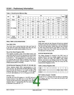
Table 1. Clock/Control Memory Map
Bit
Reg
Name
Addr.
Type
Range
7
6
5
4
3
2
1
0 (optional)
003F
0037
0036
0035
0034
0033
0032
0031
0030
Status
SR
Y2K
DW
YR
BAT
0
X
0
X
Y2K21
0
0
Y2K20
0
0
Y2K13
0
RWEL
0
WEL
0
RTCF
Y2K10
DY0
Y10
01h
19/20 20h
0-6 00h
0
0
DY2
Y12
G12
D12
H12
M12
S12
DY1
Y11
G11
D11
H11
M11
S11
Y23
0
Y22
0
Y21
0
Y20
G20
D20
H20
M20
S20
Y13
G13
D13
H13
M13
S13
0-99 00h
1-12 00h
1-31 00h
0-23 00h
0-59 00h
0-59 00h
MO
DT
G10
RTC (SRAM)
0
0
D21
H21
M21
S21
D10
HR
MN
SC
MIL
0
0
H10
M22
S22
M10
S10
0
Control
(EEPROM)
0010
BL
BP2
BP1
BP0
WD1
WD0
0
0
0
00h
REAL TIME CLOCK REGISTERS
Year 2000 (Y2K)
Leap Years
Leap years add the day February 29 and are defined
as those years that are divisible by 4.Years divisible by
100 are not leap years, unless they are also divisible
by 400. This means that the year 2000 is a leap year,
the year 2100 is not. The X1241 does not correct for
the leap year in the year 2100.
The X1241 has a century byte that “rolls over” from 19
to 20 when the years byte changes from 99 to 00. The
Y2K byte can contain only the values of 19 or 20.
Day of the Week Register (DW)
STATUS REGISTER (SR)
This register provides a Day of the Week status and
uses three bits DY2 to DY0 to represent the seven days
of the week. The counter advances in the cycle 0-1-2-
3-4-5-6-0-1-2-... The assignment of a numerical value
to a specific day of the week is arbitrary and may be
decided by the system software designer. The Clock
Default values define 0=Sunday.
The Status Register is located in the RTC area at
address 003FH. This is a volatile register only and is
used to control the WEL and RWEL write enable
latches, and read a Low Voltage Sense bit. This regis-
ter is logically separated from both the array and the
Clock/Control Registers (CCR).
Clock/Calendar Registers (YR, MO, DT, HR, MN, SC)
Table 2. Status Register (SR)
These registers depict BCD representations of the
time. As such, SC (Seconds) and MN (Minutes) range
from 00 to 59, HR (Hour) is 1 to 12 with an AM or PM
indicator (H21 bit) or 0 to 23 (with MIL = 1), DT (Date)
is 1 to 31, MO (Month) is 1 to 12, YR (year) is 0 to 99.
Addr
7
6
5
4
3
2
1
0
003Fh
BAT
0
0
0
0
0
0
0
0
0
RWEL WEL RTCF
Default
0
0
1
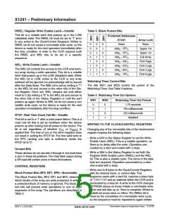
BAT: Battery Supply—Volatile
This bit set to “1” indicates that the device is operating
from V , not V . It is a read only bit and is set/
24-Hour Time
If the MIL bit of the HR register is 1, the RTC will use a
24-hour format. If the MIL bit is 0, the RTC will use
12-hour format and bit H21 will function as an AM/PM
indicator with a ‘1’ representing PM. The clock defaults
to Standard Time with H21 = 0.
BACK
CC
reset by hardware.
Characteristics subject to change without notice. 4 of 22
REV 1.1.3 2/13/01
www.xicor.com

 XICOR [ XICOR INC. ]