X1241 – Preliminary Information
Page Write
Stops and Write Modes
The X1241 has a page write operation. It is initiated in
the same manner as the byte write operation; but instead
of terminating the write cycle after the first data byte is
transferred, the master can transmit up to 63 more bytes
to the memory array and up to 7 more bytes to the
clock/control registers. (Note: Prior to writing to the
CCR, the master must write a 02h, then 06h to the sta-
tus register in two preceding operations to enable the
write operation. See “Writing to the Clock/Control Reg-
isters” on page 5.)
Stop conditions that terminate write operations must
be sent by the master after sending at least 1 full data
byte and it’s associated ACK signal. If a stop is issued
in the middle of a data byte, or before 1 full data byte +
ACK is sent, then the device will reset itself without
performing the write. The contents of the array will not
be affected.
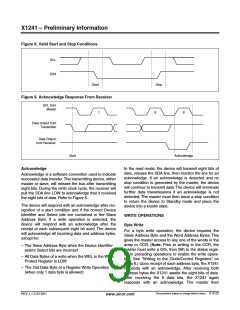
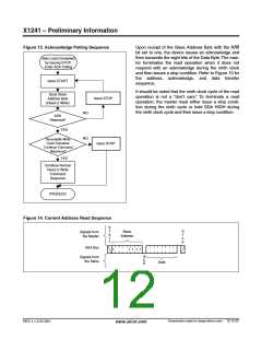
Acknowledge Polling
The disabling of the inputs during non volatile write
cycles can be used to take advantage of the typical
5ms write cycle time. Once the stop condition is issued
to indicate the end of the master’s byte load operation,
the device initiates the internal non volatile write cycle.
Acknowledge polling can be initiated immediately. To do
this, the master issues a start condition followed by the
Slave Address Byte for a write or read operation. If the
device is still busy with the non volatile write cycle then
no ACK will be returned. If the device has completed
the write operation, an ACK will be returned and the
host can then proceed with the read or write operation.
Refer to the flow chart in Figure 9.
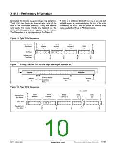
After the receipt of each byte, the X1241 responds with
an acknowledge, and the address is internally incre-
mented by one. When the counter reaches the end of
the page, it “rolls over” and goes back to the first
address on the same page. This means that the mas-
ter can write 64 bytes to a memory array page or 8
bytes to a CCR section starting at any location on that
page. If the master begins writing at location 40 of the
memory and loads 30 bytes, then the first 23 bytes are
written to addresses 40 through 63, and the last 7
bytes are written to columns 0 through 6. Afterwards,
the address counter would point to location 7 on the
page that was just written. If the master supplies more
than the maximum bytes in a page, then the previously
loaded data is over written by the new data, one byte at
a time.
READ OPERATIONS
There are three basic read operations: Current
Address Read, Random Read, and Sequential Read.
The master terminates the Data Byte loading by issuing
a stop condition, which causes the device to begin the
non volatile write cycle. As with the byte write opera-
tion, all inputs are disabled until completion of the inter-
nal write cycle. Refer to Figure 8 for the address,
acknowledge, and data transfer sequence.
Current Address Read
Internally the device contains an address counter that
maintains the address of the last word read incremented
by one. Therefore, if the last read was to address n, the
next read operation would access data from address
n+1. On power up, the sixteen bit address is initialized to
0h. In this way, a current address read can be initiated
immediately after the power on reset to download the
contents of memory starting at the first location.
Characteristics subject to change without notice. 11 of 22
REV 1.1.3 2/13/01
www.xicor.com

 XICOR [ XICOR INC. ]