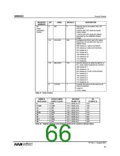
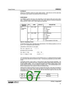
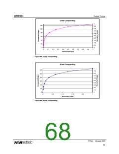
WM8983
Product Preview
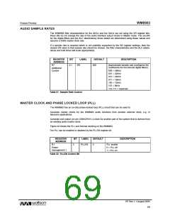
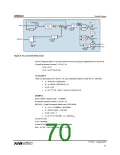
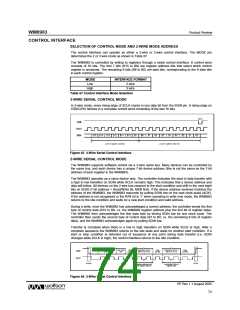
Figure 44 PLL and Clock Select Circuit
The PLL frequency ratio R = f2/f1 (see Figure 44) can be set using the register bits PLLK and PLLN.
R should be chosen to ensure 5 < PLLN < 13:
PLLN = int R
PLLK = int (224 (R-PLLN))
To calculate R:
There is a fixed divide by 4 in the PLL, f/4, and a selectable divide by N after the PLL, MCLKDIV.
•
•
•
•
f2 = SYSCLK x 4 x MCLKDIV
R = f2 / (MCLK / PRESCALE) = R
PLLN = int R
k = int ( 224 x (R – intR)) – convert k to hex for PLLK
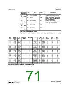
EXAMPLE:
MCLK=26MHz, required clock = 12.288MHz.
R should be chosen to ensure 5 < PLLN < 13.
MCLKDIV = 2 sets the required division rate; SYSCLK/256.
•
•
•
•
f2 = 4 x 2 x 12.288MHz = 98.304MHz.
R = 98.304 / (26/2) = 7.561846
PLLN = int R = 7
k = int ( 224 x (7.561846 – 7)) = 9426214dec
Convert k to hex:
PLLK = 8FD526h
Convert PLLK to R36, R37, R38 and R39 hex values:
R36 = 7h; R37 = 23h; R38 = 1EAh; R39 = 126h
PP Rev 1.1 August 2005
70
w

 WOLFSON [ WOLFSON MICROELECTRONICS PLC ]