WM8983
Product Preview
GENERAL PURPOSE INPUT/OUTPUT
The WM8983 has three dual purpose input/output pins.
•
•
•
CSB/GPIO1: CSB / GPIO1 pin
L2/GPIO2: Left channel line input / headphone detection input
R2/GPIO3: Right channel line input / headphone detection input
The GPIO2 and GPIO3 functions are provided for use as jack detection inputs.
The GPIO1 and GPIO2 functions are provided for use as jack detection inputs or general purpose
outputs.
The default configuration for the CSB/GPIO1 is to be an input.
When setup as an input, the CSB/GPIO1 pin can either be used as CSB or for jack detection,
depending on how the MODE pin is set.
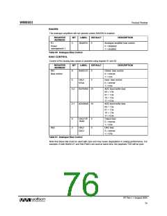
Table 55 illustrates the functionality of the GPIO1 pin when used as a general purpose output.
REGISTER
ADDRESS
BIT
LABEL
DEFAULT
DESCRIPTION
R8
2:0
GPIO1SEL
000
CSB/GPIO1 pin function select:
GPIO
000= input (CSB/jack detection:
depending on MODE setting)
Control
001 = reserved
010 = Temp ok
011 = Amute active
100 = PLL clk output
101 = PLL lock
110 = logic 0
111 = logic 1
3
GPIO1POL
OPCLKDIV
0
GPIO1 Polarity invert
0 = Non inverted
1 = Inverted
5:4
00
PLL Output clock division ratio
00 = divide by 1
01 = divide by 2
10 = divide by 3
11 = divide by 4
Table 55 CSB/GPIO Control
Note: If MODE is set to 3 wire mode, CSB/GPIO1 is used as CSB input irrespective of the
GPIO1SEL[2:0] bits.
For further details of the jack detect operation see the OUTPUT SWITCHING section.
OUTPUT SWITCHING (JACK DETECT)
When the device is operated using a 2-wire interface the CSB/GPIO1 pin can be used as a switch
control input to automatically disable one set of outputs and enable another. The L2/GPIO2 and
R2/GPIO3 pins can also be used for this purpose.
The GPIO pins have an internal de-bounce circuit when in this mode in order to prevent the output
enables from toggling multiple times due to input glitches. This de-bounce circuit is clocked from a
slow clock with period 221 x MCLK.
Note that the GPIOPOL bit is not relevant for jack detection, it is the signal detected at the pin which
is used.
The switching on/off of the outputs is fully configurable by the user. Each output, OUT1, OUT2,
OUT3 and OUT4 has
2 associated enables. OUT1_EN_0, OUT2_EN_0, OUT3_EN_0 and
OUT4_EN_0 are the output enable signals which are used if the selected jack detection pin is at
logic 0 (after de-bounce). OUT1_EN_1, OUT2_EN_1, OUT3_EN_1 and OUT4_EN_1 are the output
enable signals which are used if the selected jack detection pin is at logic 1 (after de-bounce).
PP Rev 1.1 August 2005
72
w

 WOLFSON [ WOLFSON MICROELECTRONICS PLC ]