WM8904
Pre-Production
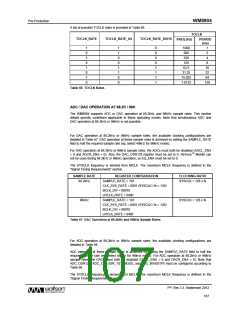
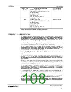
SAMPLE RATE
REGISTER CONFIGURATION
SAMPLE_RATE = 101
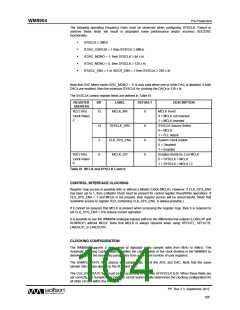
CLOCKING RATIO
SYSCLK = 128 x fs
88.2kHz
CLK_SYS_RATE = 0001 (SYSCLK / fs = 128)
BCLK_DIV = 00010
LRCLK_RATE = 040h
ADC_OSR128 = 0
ADC_128_OSR_TST_MODE = 0
ADC_BIASX1P5 = 0
SAMPLE_RATE = 101
96kHz
SYSCLK = 128 x fs
CLK_SYS_RATE = 0001 (SYSCLK / fs = 128)
BCLK_DIV = 00010
LRCLK_RATE = 040h
ADC_OSR128 = 0
ADC_128_OSR_TST_MODE = 0
ADC_BIASX1P5 = 0
Table 68 ADC Operation at 88.2kHz and 96kHz Sample Rates
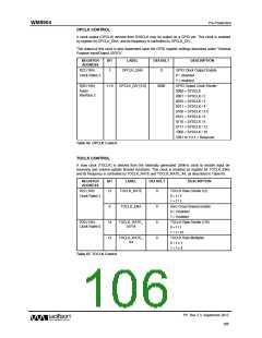
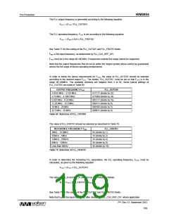
FREQUENCY LOCKED LOOP (FLL)
The integrated FLL can be used to generate SYSCLK from a wide variety of different reference
sources and frequencies. The FLL can use either MCLK, BCLK or LRCLK as its reference, which may
be a high frequency (eg. 12.288MHz) or low frequency (eg. 32,768kHz) reference. The FLL is tolerant
of jitter and may be used to generate a stable SYSCLK from a less stable input signal. The FLL
characteristics are summarised in “Electrical Characteristics”.
Note that the FLL can be used to generate a free-running clock in the absence of an external
reference source. This is described in the “Free-Running FLL Clock” section below.
The FLL is enabled using the FLL_ENA register bit. Note that, when changing FLL settings, it is
recommended that the digital circuit be disabled via FLL_ENA and then re-enabled after the other
register settings have been updated. When changing the input reference frequency FREF, it is
recommended the FLL be reset by setting FLL_ENA to 0.
The FLL_CLK_REF_SRC field allows MCLK, BCLK or LRCLK to be selected as the input reference
clock.
The field FLL_CLK_REF_DIV provides the option to divide the input reference (MCLK, BCLK or
LRCLK) by 1, 2, 4 or 8. This field should be set to bring the reference down to 13.5MHz or below. For
best performance, it is recommended that the highest possible frequency - within the 13.5MHz limit -
should be selected.
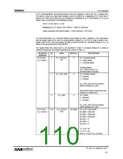
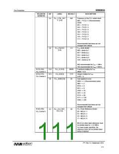
The field FLL_CTRL_RATE controls internal functions within the FLL; it is recommended that only the
default setting be used for this parameter. FLL_GAIN controls the internal loop gain and should be set
to the recommended value quoted in Table 71.
The FLL output frequency is directly determined from FLL_FRATIO, FLL_OUTDIV and the real
number represented by FLL_N and FLL_K. The field FLL_N is an integer (LSB = 1); FLL_K is the
fractional portion of the number (MSB = 0.5). The fractional portion is only valid in Fractional Mode
when enabled by the field FLL_FRACN_ENA.
It is recommended that FLL_FRACN_ENA is enabled at all times. Power consumption in the FLL is
reduced in integer mode; however, the performance may also be reduced, with increased noise or
jitter on the output.
If low power consumption is required, then FLL settings must be chosen when N.K is an integer (ie.
FLL_K = 0). In this case, the fractional mode can be disabled by setting FLL_FRACN_ENA = 0.
For best FLL performance, a non-integer value of N.K is required. In this case, the fractional mode
must be enabled by setting FLL_FRACN_ENA = 1. The FLL settings must be adjusted, if necessary,
to produce a non-integer value of N.K.
PP, Rev 3.3, September 2012
108
w

 WOLFSON [ WOLFSON MICROELECTRONICS PLC ]