WM8904
Pre-Production
The following operating frequency limits must be observed when configuring SYSCLK. Failure to
observe these limits will result in degraded noise performance and/or incorrect ADC/DAC
functionality.
.
.
.
.
.
SYSCLK 3MHz
If DAC_OSR128 = 1 then SYSCLK 6MHz
If DAC_MONO = 1, then SYSCLK 64 x fs
If DAC_MONO = 0, then SYSCLK 128 x fs
If ADCL_ENA = 1 or ADCR_ENA = 1 then SYSCLK 256 x fs
Note that DAC Mono mode (DAC_MONO = 1) is only valid when one or other DAC is disabled. If both
DACs are enabled, then the minimum SYSCLK for clocking the DACs is 128 x fs.
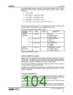
The SYSCLK control register fields are defined in Table 61.
REGISTER
ADDRESS
BIT
LABEL
DEFAULT
DESCRIPTION
MCLK Invert
R22 (16h)
15
MCLK_INV
0
Clock Rates
2
0 = MCLK not inverted
1 = MCLK inverted
SYSCLK Source Select
0 = MCLK
14
2
SYSCLK_SRC
CLK_SYS_ENA
MCLK_DIV
0
0
0
1 = FLL output
System Clock enable
0 = Disabled
1 = Enabled
R20 (14h)
Enables divide by 2 on MCLK
0 = SYSCLK = MCLK
1 = SYSCLK = MCLK / 2
0
Clock Rates
0
Table 61 MCLK and SYSCLK Control
CONTROL INTERFACE CLOCKING
Register map access is possible with or without a Master Clock (MCLK). However, if CLK_SYS_ENA
has been set to 1, then a Master Clock must be present for control register Read/Write operations. If
CLK_SYS_ENA = 1 and MCLK is not present, then register access will be unsuccessful. (Note that
read/write access to register R22, containing CLK_SYS_ENA, is always possible.)
If it cannot be assured that MCLK is present when accessing the register map, then it is required to
set CLK_SYS_ENA = 0 to ensure correct operation.
It is possible to use the WM8904 analogue bypass paths to the differential line outputs (LON/LOP and
RON/ROP) without MCLK. Note that MCLK is always required when using HPOUTL, HPOUTR,
LINEOUTL or LINEOUTR.
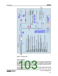
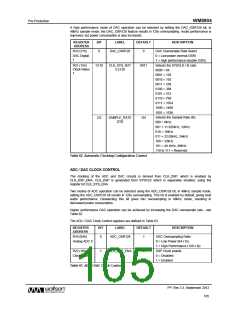
CLOCKING CONFIGURATION
The WM8904 supports a wide range of standard audio sample rates from 8kHz to 48kHz. The
Automatic Clocking Configuration simplifies the configuration of the clock dividers in the WM8904 by
deriving most of the necessary parameters from a minimum number of user registers.
The SAMPLE_RATE field selects the sample rate, fs, of the ADC and DAC. Note that the same
sample rate always applies to the ADC and DAC.
The CLK_SYS_RATE field must be set according to the ratio of SYSCLK to fs. When these fields are
set correctly, the Sample Rate Decoder circuit automatically determines the clocking configuration for
all other circuits within the WM8904.
PP, Rev 3.3, September 2012
104
w

 WOLFSON [ WOLFSON MICROELECTRONICS PLC ]