Pre-Production
WM8904
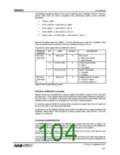
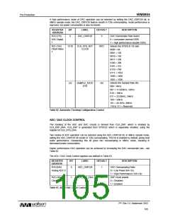
A high performance mode of DAC operation can be selected by setting the DAC_OSR128 bit; in
48kHz sample mode, the DAC_OSR128 feature results in 128x oversampling. Audio performance is
improved, but power consumption is also increased.
REGISTER
ADDRESS
BIT
LABEL
DEFAULT
DESCRIPTION
R33 (21h)
DAC Oversample Rate Select
0 = Low power (normal OSR)
1 = High performance (double OSR)
Selects the SYSCLK / fs ratio
0000 = 64
6
DAC_OSR128
0
DAC Digital
1
R21 (15h)
Clock Rates
1
13:10
CLK_SYS_RAT
E [3:0]
0011
0001 = 128
0010 = 192
0011 = 256
0100 = 384
0101 = 512
0110 = 768
0111 = 1024
1000 = 1408
1001 = 1536
Selects the Sample Rate (fs)
000 = 8kHz
2:0
SAMPLE_RATE
[2:0]
101
001 = 11.025kHz, 12kHz
010 = 16kHz
011 = 22.05kHz, 24kHz
100 = 32kHz
101 = 44.1kHz, 48kHz
110 to 111 = Reserved
Table 62 Automatic Clocking Configuration Control
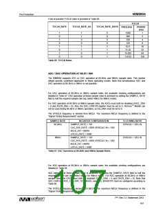
ADC / DAC CLOCK CONTROL
The clocking of the ADC and DAC circuits is derived from CLK_DSP, which is enabled by
CLK_DSP_ENA. CLK_DSP is generated from SYSCLK which is separately enabled, using the
register bit CLK_SYS_ENA.
Two modes of ADC operation can be selected using the ADC_OSR128 bit; in 48kHz sample mode,
setting the ADC_OSR128 bit results in 128x oversampling. This bit is enabled by default, giving best
audio performance. Deselecting this bit gives 64x oversampling in 48kHz mode, resulting in
decreased power consumption.
Higher performance DAC operation can be achieved by increasing the DAC oversample rate - see
Table 62.
The ADC / DAC Clock Control registers are defined in Table 63.
REGISTER
ADDRESS
BIT
LABEL
DEFAULT
DESCRIPTION
R10 (0Ah)
ADC Oversampling Ratio
0 = Low Power (64 x fs)
1 = High Performance (128 x fs)
DSP Clock enable
0
ADC_OSR128
1
Analog ADC 0
R22 (16h)
1
CLK_DSP_ENA
0
Clock Rates 2
0 = Disabled
1 = Enabled
Table 63 ADC / DAC Clock Control
PP, Rev 3.3, September 2012
105
w

 WOLFSON [ WOLFSON MICROELECTRONICS PLC ]