WM8904
Pre-Production
DESCRIPTION
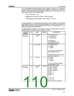
FLL Clock source
REGISTER
ADDRESS
BIT
LABEL
DEFAULT
1:0
FLL_CLK_REF_
SRC [1:0]
00
00 = MCLK
01 = BCLK
10 = LRCLK
11 = Reserved
Table 71 FLL Register Map
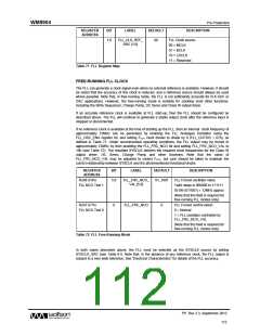
FREE-RUNNING FLL CLOCK
The FLL can generate a clock signal even when no external reference is available. However, it should
be noted that the accuracy of this clock is reduced, and a reference source should always be used
where possible. Note that, in free-running mode, the FLL is not sufficiently accurate for hi-fi ADC or
DAC applications. However, the free-running mode is suitable for clocking most other functions,
including the Write Sequencer, Charge Pump, DC Servo and Class W output driver.
If an accurate reference clock is available at FLL start-up, then the FLL should be configured as
described above. The FLL will continue to generate a stable output clock after the reference input is
stopped or disconnected.
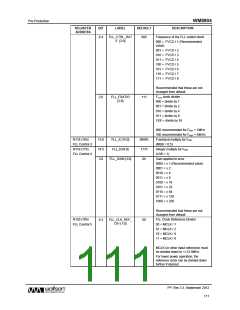
If no reference clock is available at the time of starting up the FLL, then an internal clock frequency of
approximately 12MHz can be generated by enabling the FLL Analogue Oscillator using the
FLL_OSC_ENA register bit, and setting FOUT clock divider to divide by 8 (FLL_OUTDIV = 07h), as
defined in Table 71. Under recommended operating conditions, the FLL output may be forced to
approximately 12MHz by then enabling the FLL_FRC_NCO bit and setting FLL_FRC_NCO_VAL to
19h (see Table 72). The resultant SYSCLK delivers the required clock frequencies for the Class W
output driver, DC Servo, Charge Pump and other functions. Note that the value of
FLL_FRC_NCO_VAL may be adjusted to control FOUT, but care should be taken to maintain the
correct relationship between SYSCLK and the aforementioned functional blocks.
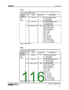
REGISTER
ADDRESS
BIT
LABEL
DEFAULT
DESCRIPTION
R248 (F8h)
FLL Forced oscillator value
5:0
FLL_FRC_NCO_
VAL [5:0]
01_1001
FLL NCO Test 1
Valid range is 000000 to 111111
0x19h (011001) = 12MHz approx
(Note that this field is required for
free-running FLL modes only)
R247 (F7h)
FLL Forced control select
0 = Normal
0
FLL_FRC_NCO
0
FLL NCO Test 0
1 = FLL oscillator controlled by
FLL_FRC_NCO_VAL
(Note that this field is required for
free-running FLL modes only)
Table 72 FLL Free-Running Mode
In both cases described above, the FLL must be selected as the SYSCLK source by setting
SYSCLK_SRC (see Table 61). Note that, in the absence of any reference clock, the FLL output is
subject to a very wide tolerance. See “Electrical Characteristics” for details of the FLL accuracy.
PP, Rev 3.3, September 2012
112
w

 WOLFSON [ WOLFSON MICROELECTRONICS PLC ]