Pre-Production
WM8904
LOOPBACK
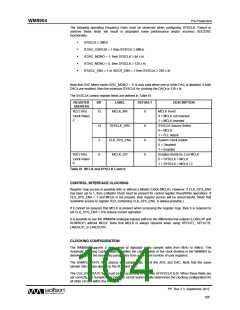
Setting the LOOPBACK register bit enables digital loopback. When this bit is set, the ADC digital data
output is routed to the DAC digital data input path. The digital audio interface input (DACDAT) is not
used when LOOPBACK is enabled.
REGISTER
ADDRESS
BIT
LABEL
DEFAULT
DESCRIPTION
R24 (18h)
Digital Loopback Function
0 = No loopback
8
LOOPBACK
0
Audio
Interface 0
1 = Loopback enabled (ADC data output
is directly input to DAC data input).
Table 59 Loopback Control
Note: When the digital sidetone is enabled, ADC data will also be added to DAC digital data input
path within the Digital Mixing circuit. This applies regardless of whether LOOPBACK is enabled.
DIGITAL PULL-UP AND PULL-DOWN
The WM8904 provides integrated pull-up and pull-down resistors on each of the MCLK, DACDAT,
LRCLK and BCLK pins. This provides a flexible capability for interfacing with other devices. Each of
the pull-up and pull-down resistors can be configured independently using the register bits described
in Table 60.
REGISTER
ADDRESS
BIT
LABEL
DEFAULT
DESCRIPTION
R126 (7Eh)
Digital Pulls
MCLK pull-up resistor enable
0 = pull-up disabled
7
MCLK_PU
0
1 = pull-up enabled
MCLK pull-down resistor enable
0 = pull-down disabled
1 = pull-down enabled
6
5
4
3
2
1
0
MCLK_PD
DACDAT_PU
DACDAT_PD
LRCLK_PU
LRCLK_PD
BCLK_PU
0
0
0
0
0
0
0
DACDAT pull-up resistor enable
0 = pull-up disabled
1 = pull-up enabled
DACDAT pull-down resistor enable
0 = pull-down disabled
1 = pull-down enabled
LRCLK pull-up resistor enable
0 = pull-up disabled
1 = pull-up enabled
LRCLK pull-down resistor enable
0 = pull-down disabled
1 = pull-down enabled
BCLK pull-up resistor enable
0 = pull-up disabled
1 = pull-up enabled
BCLK pull-down resistor enable
0 = pull-down disabled
1 = pull-down enabled
BCLK_PD
Table 60 Digital Audio Interface Pull-Up and Pull-Down Control
PP, Rev 3.3, September 2012
101
w

 WOLFSON [ WOLFSON MICROELECTRONICS PLC ]