WM8904
Pre-Production
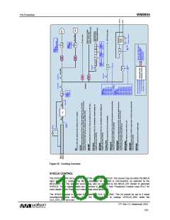
CLOCKING AND SAMPLE RATES
The internal clocks for the WM8904 are all derived from a common internal clock source, SYSCLK.
This clock is the reference for the ADCs, DACs, DSP core functions, digital audio interface, DC servo
control and other internal functions.
SYSCLK can either be derived directly from MCLK, or may be generated from a Frequency Locked
Loop (FLL) using MCLK, BCLK or LRCLK as a reference. Many commonly-used audio sample rates
can be derived directly from typical MCLK frequencies; the FLL provides additional flexibility for a
wide range of MCLK frequencies. To avoid audible glitches, all clock configurations must be set up
before enabling playback. The FLL can be used to generate a free-running clock in the absence of an
external reference source; see “Frequency Locked Loop (FLL)” for further details.
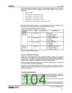
The WM8904 supports automatic clocking configuration. The programmable dividers associated with
the ADCs, DACs, DSP core functions and DC servo are configured automatically, with values
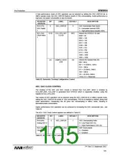
determined from the CLK_SYS_RATE and SAMPLE_RATE fields. The user must also configure the
OPCLK (if required), the TOCLK (if required) and the Digital Audio Interface.
Oversample rates of 64fs or 128fs are supported (based on a 48kHz sample rate).
A 256kHz clock, supporting a number of internal functions, is derived from SYSCLK.
The DC servo control is clocked from SYSCLK.
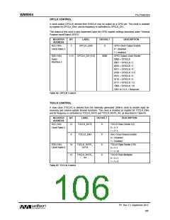
A GPIO Clock, OPCLK, can be derived from SYSCLK and output on a GPIO pin to provide clocking
to other devices. This clock is enabled by OPCLK_ENA and controlled by OPCLK_DIV.
A slow clock, TOCLK, is used to de-bounce the button/accessory detect inputs, and to set the timeout
period for volume updates when zero-cross detect is used. This clock is enabled by TOCLK_ENA and
controlled by TOCLK_RATE, TOCLK_RATE_X4 and TOCLK_RATE_DIV16.
In master mode, BCLK is derived from SYSCLK via a programmable divider set by BCLK_DIV. In
master mode, the LRCLK is derived from BCLK via a programmable divider LRCLK_RATE. The
LRCLK can be derived from an internal or external BCLK source, allowing mixed master/slave
operation.
The control registers associated with Clocking and Sample Rates are shown in Table 61 to Table 65.
The overall clocking scheme for the WM8904 is illustrated in Figure 59.
PP, Rev 3.3, September 2012
102
w

 WOLFSON [ WOLFSON MICROELECTRONICS PLC ]