WM8904
Pre-Production
Note that the WM8904 is a 24-bit device. In 32-bit mode (AIF_WL=11), the 8 LSBs are ignored on the
receiving side and not driven on the transmitting side.
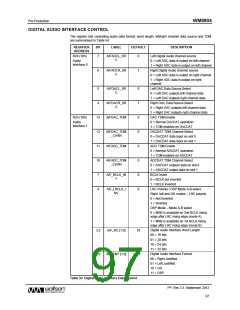
AUDIO INTERFACE OUTPUT TRI-STATE
Register bit AIF_TRIS can be used to tri-state the audio interface pins as described in Table 55. All
digital audio interface pins will be tri-stated by this function, regardless of the state of other registers
which control these pin configurations.
REGISTER
ADDRESS
BIT
LABEL
DEFAULT
DESCRIPTION
R25 (19h)
Audio Interface Tristate
8
AIF_TRIS
0
Audio
Interface 1
0 = Audio interface pins operate normally
1 = Tristate all audio interface pins
Table 55 Digital Audio Interface Tri-State Control
BCLK AND LRCLK CONTROL
The audio interface can be programmed to operate in master mode or slave mode using the
BCLK_DIR and LRCLK_DIR register bits. In master mode, the BCLK and LRCLK signals are
generated by the WM8904 when any of the ADCs or DACs is enabled. In slave mode, the BCLK and
LRCLK clock outputs are disabled by default to allow another digital audio interface to drive these
pins.
It is also possible to force the BCLK or LRCLK signals to be output using BCLK_DIR and
LRCLK_DIR, allowing mixed master and slave modes. The BCLK_DIR and LRCLK_DIR fields are
defined in Table 56.
REGISTER
ADDRESS
BIT
LABEL
DEFAULT
DESCRIPTION
R25 (19h)
Audio Interface BCLK Direction
0 = BCLK is input
6
BCLK_DIR
0
Audio
Interface 1
1 = BCLK is output
R26 (1Ah)
BCLK Frequency (Master Mode)
00000 = SYSCLK
4:0
BCLK_DIV
[4:0]
0_0100
Audio
Interface 2
00001 = SYSCLK / 1.5
00010 = SYSCLK / 2
00011 = SYSCLK / 3
00100 = SYSCLK / 4 (default)
00101 = SYSCLK / 5
00110 = SYSCLK / 5.5
00111 = SYSCLK / 6
01000 = SYSCLK / 8
01001 = SYSCLK / 10
01010 = SYSCLK / 11
01011 = SYSCLK / 12
01100 = SYSCLK / 16
01101 = SYSCLK / 20
01110 = SYSCLK / 22
01111 = SYSCLK / 24
10000 = SYSCLK / 25
10001 = SYSCLK / 30
10010 = SYSCLK / 32
10011 = SYSCLK / 44
10100 = SYSCLK / 48
PP, Rev 3.3, September 2012
98
w

 WOLFSON [ WOLFSON MICROELECTRONICS PLC ]