Production Data
WM8805
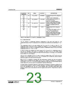
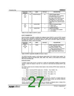
REGISTER
ADDRESS
BIT
LABEL
DEFAULT
DESCRIPTION
R3
PLL1
03h
R4
7:0
PLL_K[7:0]
00100001
Fractional (K) part of PLL frequency
ratio (R).
Value K is one 22-digit binary
number spread over registers R3,
R4 and R5 as shown.
7:0
5:0
3:0
PLL_K[15:8]
PLL_K[21:16]
PLL_N[3:0]
11111101
00110110
0111
PLL2
04h
R5
Note: PLL_K must be set to
specific values when the S/PDIF
receiver is used. Refer to S/PDIF
Receiver clocking section for
details.
PLL3
05h
R6
Integer (N) part of PLL frequency
ratio (R).
PLL4
06h
Use values in the range 5 ≤ PLL_N
≤ 13 as close as possible to 8
Note: PLL_N must be set to
specific values when the S/PDIF
receiver is used. Refer to S/PDIF
Receiver clocking section for
details.
Table 21 User Mode PLL_K and PLL_N Multiplier Control
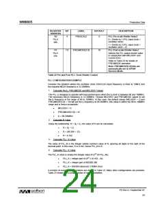
PLL CONFIGURATION
The PLL performs a configurable frequency multiplication of the input clock signal (f1). The
multiplication factor of the PLL (denoted by ‘R’) is variable and is defined by the relationship: R = (f2 ÷
f1).
The multiplication factor is set using register bits PLL_N and PLL_K (refer to Table 21). The
multiplication effect of both the N and K multipliers are additive (i.e. if N is configured to provide a
multiplication factor of 8 and K is configured to provide a multiplication factor of 0.192, the overall
multiplication factor is 8 + 0.192 = 8.192).
In order to choose and configure the correct values for PLL_N and PLL_K, multiplication factor R
must first be calculated. Once value R is calculated, the value of PLL_N is the integer (whole
number) value of R, ignoring all digits to the right of the decimal point. For example, if R is calculated
to be 8.196523, PLL_N is simply 8.
Once PLL_N is calculated, the PLL_K value is simply the integer value of (222 (R-PLL_N)). For
example, if R is 8.196523 and PLL_N is 8, PLL_K is therefore (222 (8.196523-8)), which is 824277
(ignoring all digits to the right of the decimal point).
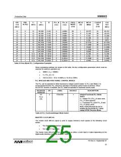
Note: the PLL is designed to operate with best performance (shortest lock time and optimum
stability) when f2 is between 90 and 100MHz and PLL_N is 8. However, acceptable PLL_N values lie
in the range 5 ≤ PLL_N ≤ 13. Do not use values outwith this range and it is recommended that the
chosen value of PLL_N is as close to 8 as possible for optimum performance.
An output divider is provided to allow the f2 clock signal to be divided to a frequency suitable for use
as the source for the MCLK, CLKOUT or S/PDIF transmitter. The divider output is configurable and is
set by the FREQMODE bits. The PLL is also equipped with a pre-scale divider which offers
frequency divide by one or two before the OSCCLK signal is fed to the PLL. Please refer to Table 22
for details.
PD Rev 4.1 September 07
23
w

 WOLFSON [ WOLFSON MICROELECTRONICS PLC ]