Production Data
WM8805
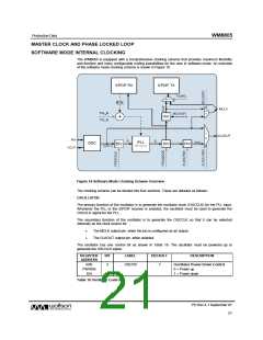
OSC
CLK
PRE-
SCALE
F1
F2
R
PLL_N
PLL_K
FREQ
MODE
MCLK
DIV
MCLK
(MHz)
CLKOUT
DIV
CLK
OUT
(MHz)
(MHz)
(Hex)
(Hex)
[1:0]
[1:0]
(MHz)
(MHz)
12
12
12
12
12
24
24
24
24
24
27
27
27
27
0
0
0
0
0
1
1
1
1
1
1
1
1
1
12
12
98.304
98.304
98.304
98.304
98.304
90.3168
90.3168
90.3168
90.3168
90.3168
98.304
98.304
90.3168
90.3168
8.192
8.192
8
8
8
8
8
7
7
7
7
7
7
7
6
6
C49BA
C49BA
C49BA
C49BA
C49BA
21B089
21B089
21B089
21B089
21B089
1208A5
1208A5
2C2B24
2C2B24
00
10
10
10
10
01
10
10
10
10
10
10
10
10
1
0
1
0
1
0
0
1
0
1
0
1
0
1
24.576
12.288
6.144
01
00
01
10
11
00
00
01
10
11
01
10
01
10
49.152
24.576
12.288
6.144
12
8.192
12
8.192
12.288
6.144
12
8.192
3.072
12
7.5264
7.5264
7.5264
7.5264
7.5264
7.2818
7.2818
6.6901
6.6901
22.5792
11.2896
5.6448
11.2896
5.6448
12.288
6.144
45.1584
22.5792
11.2896
5.6448
2.8224
12.288
6.144
12
12
12
12
13.5
13.5
13.5
13.5
11.2896
5.6448
11.2896
5.6448
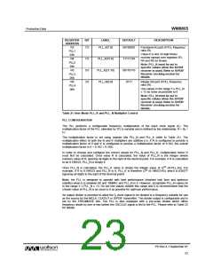
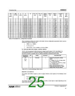
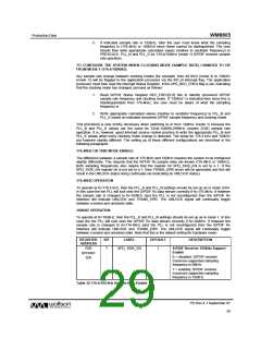
Table 23 User Mode PLL Configuration Examples
When considering settings not shown in this table, the key configuration parameters which must be
selected for optimum operation are:
•
•
•
90MHz ≤ f2 ≤ 100MHz
5 ≤ PLL_N ≤ 13
OSCCLOCK = 10 to 14.4MHz or 16.28 to 27MHz
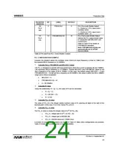
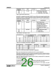
PLL INTEGER AND FRACTIONAL CONTROL MODES
The PLL can be operated in either fractional or integer control modes. In PLL User Mode, it is
recommended that the PLL should be operated in fractional control mode at all times. When
the S/PDIF receiver is enabled, the PLL must be operated in fractional control mode.
REGISTER
ADDRESS
BIT
LABEL
DEFAULT
DESCRIPTION
R7
PLL5
07h
2
FRACEN
1
Integer/Fractional PLL Mode
Select
0 = Integer PLL (PLL_N value used,
PLL_K value ignored)
1 = Fractional PLL (both PLL_N and
PLL_K values used)
Note: FRACEN must be set to
enable the fractional PLL when
using S/PDIF Receive Mode.
Table 24 PLL Fractional/Integer Mode Select
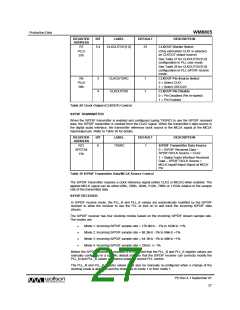
MASTER CLOCK (MCLK)
The master clock (MCLK) signal is used to supply reference clock signals to the following circuit
blocks:
•
•
The Digital Audio Interface
The S/PDIF Transmitter
The master clock (MCLK) pin can be configured as either a clock input or output depending on the
digital audio interface mode as shown in Table 25.
PD Rev 4.1 September 07
25
w

 WOLFSON [ WOLFSON MICROELECTRONICS PLC ]