Production Data
WM8805
DIGITAL ROUTING CONTROL
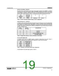
See page 20 for a full description of the signal routing options available in the WM8805. In Software
control mode the values set in registers TXSRC and RXINSEL determine the S/PDIF Rx data source
and destination. In hardware control mode the device can receive data only from RX0 but can set the
value of TXSRC directly using the CSB pin. This determines the S/PDIF transmitter data source
PIN
REGISTER
0
1
(HARDWARE
MODE)
(SOFTWARE
MODE)
CSB
TXSRC
S/PDIF Rx
AIF Rx
Table 15 S/PDIF Transmitter Digital Routing Control Configuration
AUDIO INTERFACE CONTROL
In software control mode the audio data word length and audio data format can be set independently
for the receiver and transmitter sides of the interface. However, in hardware control mode both sides
of the interface are combined and the configuration is set using SDOUT and GPO0 pins as described
in Table 6 and Table 16. Note that AIF_CONF[1:0] configures the audio interface when the device
operates in hardware mode.
GPO0 /
SDOUT /
DESCRIPTION
AIFCONF[1]
AIFCONF[0]
0
0
1
1
0
1
0
1
16-bit I2S
24-bit I2S
24-bit Left Justified With Flags
16-bit Right Justified
Table 16 Digital Audio Interface Control in Hardware Control Mode
STATUS INFORMATION
In hardware control mode the WM8805 outputs a selection of status flags for the user. Table 17
describes the flags which are available and the output pins on which they are available.
PIN
SCLK
SDOUT
CSB
STATUS FLAG
TRANS_ERR
NON_AUDIO
UNLOCK
GPO0
GEN_FLAG
Table 17 Hardware Control Mode Status Flag Configuration
A full description of the status flags is given in Table 45.
PD Rev 4.1 September 07
19
w

 WOLFSON [ WOLFSON MICROELECTRONICS PLC ]