Production Data
WM8805
DEVICE DESCRIPTION
INTRODUCTION
FEATURES
•
•
•
•
•
•
•
•
•
•
IEC-60958-3 compatible with 32 to 192k frames/s support.
Supports AES-3 data frames.
Support for reception and transmission of S/PDIF data.
Clock synthesis PLL with reference clock input and low jitter output.
Supports input reference clock frequencies from 10MHz to 27MHz.
Dedicated high drive clock output pin.
Register controlled channel status bit configuration.
Register read-back of recovered channel status bits and error flags.
Detection of non-audio data, sample rate and de-emphasis.
Programmable GPOs for error flags and frame status flags.
The WM8805 is an IEC-60958 compatible S/PDIF transceiver with support for up to eight received
S/PDIF data streams and one transmitted S/PDIF data stream.
The receiver performs data and clock recovery, and transmits recovered data from the chip either
through the digital audio interface or, alternatively, the device can loop the received S/PDIF data
back out through the S/PDIF transmitter producing a de-jittered S/PDIF transmit data stream. The
recovered clock may be routed to a high drive output pin for external use. If there is no S/PDIF input
data stream the PLL can be configured to output all standard MCLK frequencies or it can be
configured to maintain the frequency of the last received S/PDIF data stream.
The transmitter generates S/PDIF frames where audio data may be sourced from the S/PDIF
receiver or the digital audio interface. Timing for the S/PDIF transmitter interface can be sourced
from the internally derived MCLK in loop through mode or it can be taken from an external source.
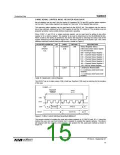
S/PDIF FORMAT
S/PDIF is a serial, bi-phase-mark encoded data stream. An S/PDIF frame consists of two sub-
frames. Each sub-frame is made up of:
•
Preamble – a synchronization pattern used to identify the start of a 192-frame block or sub-
frame
•
•
•
•
•
•
4-bit Auxiliary Data (AUX) – ordered LSB to MSB
20-bit Audio Data (24-bit when combined with AUX) – ordered LSB to MSB
Validity Bit – a 1 indicates invalid data in the associated sub-frame
User Bit – over 192-frames, this forms a User Data Block
Channel Bit – over 192-frames, this forms a Channel Status Block
Parity Bit – used to maintain even parity over the sub-frame (not including the preamble)
An S/PDIF Block consists of 192 frames. Channel and user blocks are incorporated within the 192-
frame S/PDIF Block. For Consumer mode only the first 40-frames are used to make up the Channel
and User blocks. Figure 6 illustrates the S/PDIF format. The WM8805 does not support transmission
of user channel data. Received user channel data may be accessed via GPO pins.
PD Rev 4.1 September 07
11
w

 WOLFSON [ WOLFSON MICROELECTRONICS PLC ]