Production Data
WM8805
3-WIRE SERIAL CONTROL MODE REGISTER READ-BACK
Not all registers can be read. Only the device ID (registers R0, R1 and R2) and the status registers
can be read. These status registers are labelled as “read only” in the Register Map section.
The read-only status registers can be read back via the SDOUT pin. The registers can be read by
one of two methods, selected by the CONT register bit and the ‘W’ control bit. The oscillator must be
powered up before 3-wire control interface read-back is possible.
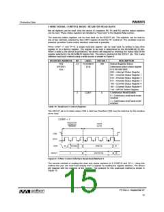
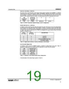
When CONT =1 and ‘W’=0, a single read-only register can be read back by writing to any other
register or to a dummy register. The register to be read is determined by the READMUX[2:0] bits.
When a write to the device is performed, the device will respond by returning the status byte of the
register selected by the READMUX register bits. The data is returned on the SDOUT pin. This 3-wire
interface read-back method using a write access is shown in Figure 9.
REGISTER ADDRESS
BIT
LABEL
READMUX
[2:0]
DEFAULT
DESCRIPTION
R29
SPDRX1
1Dh
2:0
000
Status Register Select
Determines which status register
is to be read back:
000 = Interrupt Status Register
001 = Channel Status Register 1
010 = Channel Status Register 2
011 = Channel Status Register 3
100 = Channel Status Register 4
101 = Channel Status Register 5
110 = S/PDIF Status Register
Continuous Read Enable
3
CONT
0
0 = Continuous read-back mode
disabled
1 = Continuous read-back mode
enabled
Table 10 Read-back Control Register
The SDOUT pin is tri-state unless CSB is held low; therefore CSB must be held low for the duration
of the read.
CONT = 1
REGISTER
DATA
ADDRESS
(R/W=0)
BYTE
CSB
SCLK
SDIN
W
REGA[6:0]
X
DIN[7:0]
X
SDOUT
DOUT[7:0]
X
Figure 9 3-Wire Control Interface Read-Back Method 1
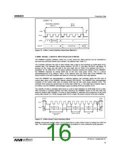
The second method of reading the read only status registers is If CONT=0 and ‘W’=1. Using this
method the user can read back directly from a register by reading the register address. The device
will respond with the contents of the register. The protocol for this read-back method is shown in
Figure 10.
PD Rev 4.1 September 07
15
w

 WOLFSON [ WOLFSON MICROELECTRONICS PLC ]