WM8805
Production Data
CONTROL INTERFACE OPERATION
Control of the WM8805 is implemented in either hardware control mode or software control mode.
The method of control is determined by sampling the state of the SDIN/HWMODE pin at power up or
at a hardware reset. If SDIN/HWMODE is low during power up the device is configured in hardware
control mode, otherwise the device is configured in software control mode.
SDIN/HWMODE
0
1
Hardware mode
Software mode
Table 8 Hardware or Software Mode Select
Software control is achieved using a 3-wire (3-wire write, 4-wire read) or a 2-wire serial interface.
The serial interface format is configured by sampling the state of the GPO0/SWIFMODE pin on
power up or at a hardware reset. If the GPO0/SWIFMODE pin is low the interface is configured in 2-
wire mode, otherwise the interface is configured in 3-wire SPI compatible mode.
GPO0/SWIFMODE
0
1
2-wire interface
3-wire interface
Table 9 Software Mode Control Interface Select
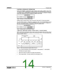
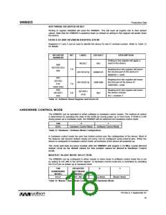
3-WIRE (SPI COMPATIBLE) SERIAL CONTROL MODE – REGISTER WRITE
SDIN is used for the program data, SCLK is used to clock in the program data and CSB is used to
latch in the program data. SDIN is sampled on the rising edge of SCLK. The 3-wire interface write
protocol is shown in Figure 8.
Figure 8 3-Wire Serial Interface Register Write Protocol
•
•
•
•
W is a control bit indicating a read or write operation. 0 =write operation, 1 = read operation
REGA[6:0] is the register Address.
DIN[7:0] is the data to be written to the register being addressed.
CSB is edge sensitive – the data is latched on the rising edge of CSB.
PD Rev 4.1 September 07
14
w

 WOLFSON [ WOLFSON MICROELECTRONICS PLC ]