Product Preview
WM8774
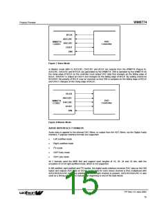
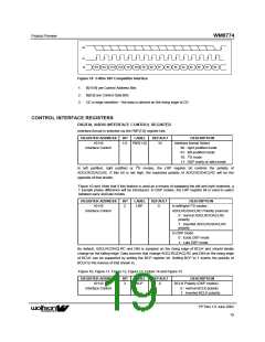
BCLK
ADCLRC
DACLRC
DOUT
DVD
Controller
WM8774
CODEC
DIN
Figure 7 Slave Mode
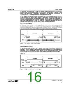
In Master mode (MS=1) ADCLRC, DACLRC and BCLK are outputs from the WM8774 (Figure 8).
ADCLRC, DACLRC and BITCLK are generated by the WM8774. DIN is sampled by the WM8774 on
the rising edge of BCLK so the controller must output DAC data that changes on the falling edge of
BCLK. ADCDAT is output on DOUT and changes on the falling edge of BCLK. By setting control bit
BCLKINV the polarity of BCLK may be reversed so that DIN is sampled on the falling edge of BCLK
and DOUT changes on the rising edge of BCLK.
BCLK
ADCLRC
DVD
Controller
WM8774
CODEC
DACLRC
DOUT
DIN
Figure 8 Master Mode
AUDIO INTERFACE FORMATS
Audio data is applied to the internal DAC filters, or output from the ADC filters, via the Digital Audio
Interface. 5 popular interface formats are supported:
•
•
•
•
•
Left Justified mode
Right Justified mode
I2S mode
DSP Early mode
DSP Late mode
All 5 formats send the MSB first and support word lengths of 16, 20, 24 and 32 bits, with the
exception of 32 bit right justified mode, which is not supported.
In left justified, right justified and I2S modes, the digital audio interface receives DAC data on the DIN
inputs and outputs ADC data on DOUT. Audio Data for each stereo channel is time multiplexed with
ADCLRC/DACLRC indicating whether the left or right channel is present. ADCLRC/DACLRC is also
used as a timing reference to indicate the beginning or end of the data words.
PP Rev 1.0 June 2002
ꢀꢀ
15

 WOLFSON [ WOLFSON MICROELECTRONICS PLC ]