WM8774
Product Preview
BCLK is also generated by the WM8774. The frequency of BCLK depends on the mode of operation.
In 128/192fs modes (DACRATE=000 or 001) BCLK
= MCLK/2. In 256/384/512fs modes
(ADCRATE/DACRATE=010 or 011, 100 or 101) BCLK = MCLK/4. However if DSP mode is selected
as the audio interface mode then BCLK=MCLK. This is to ensure that there are sufficient BCLKs to
clock in all eight channels. Note that DSP mode cannot be used in 128fs mode for word lengths
greater than 16 bits or in 192fs mode for word lengths greater than 24 bits.
ZERO DETECT
The WM8774 has a zero detect circuit for each channel, which detects when 1024 consecutive zero
samples have been input. Two zero flag outputs (ZFLAGL and ZFLAGR) may be programmed to
output the zero detect signals (see Table 8) which may then be used to control external muting
circuits. A ‘1’ on ZFLAGL or ZFLAGR indicates a zero detect. The zero detect may also be used to
automatically enable the PGA mute by setting IZD. The zero flag output may be disabled by setting
DZFM to 00. The zero flag signal for each DAC channel will only be enabled if that channel is
enabled as an input to the output summing stage.
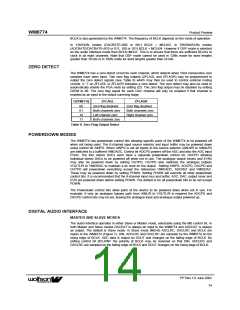
DZFM[1:0]
ZFLAGL
ZFLAGR
Zero flag disabled
Both channels zero
Right channel zero
-
00
01
10
11
Zero flag disabled
Both channels zero
Left channel zero
Both channels zero
Table 8 Zero Flag Output Select
POWERDOWN MODES
The WM8774 has powerdown control bits allowing specific parts of the WM8774 to be powered off
when not being used. The 8-channel input source selector and input buffer may be powered down
using control bit AINPD. When AINPD is set all inputs to the source selector (AIN1l/R to AIN8L/R)
are switched to a buffered VMIDADC. Control bit ADCPD powers off the ADC and also the ADC input
PGAs. The four stereo DACs each have a separate powerdown control bit, DACPD allowing
individual stereo DACs to be powered off when not in use. The analogue output mixers and EVRs
may also be powered down by setting OUTPD. OUTPD also switches the analogue outputs
VOUTL/R to VMIDDAC to maintain a dc level on the output. Setting AINPD, ADCPD, DACPD and
OUTPD will powerdown everything except the references VMIDADC, ADCREF and VMIDDAC.
These may be powered down by setting PDWN. Setting PDWN will override all other powerdown
control bits. It is recommended that the 8-channel input mux and buffer, ADC, DAC, output mixer and
EVR are powered down before setting PDWN. The default is for all powerdown bits to be set except
PDWN.
The Powerdown control bits allow parts of the device to be powered down when not in use. For
example, if only an analogue bypass path from AINL/R to VOUTL/R is required the ADCPD and
DACPD control bits may be set, leaving the analogue input and analogue output powered up.
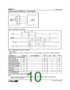
DIGITAL AUDIO INTERFACE
MASTER AND SLAVE MODES
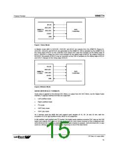
The audio interface operates in either Slave or Master mode, selectable using the MS control bit. In
both Master and Slave modes DACDAT is always an input to the WM8774 and ADCDAT is always
an output. The default is Slave mode. In Slave mode (MS=0) ADCLRC, DACLRC and BCLK are
inputs to the WM8774 (Figure 7). DIN, ADCLRC and DACLRC are sampled by the WM8774 on the
rising edge of BCLK. ADC data is output on DOUT and changes on the falling edge of BCLK. By
setting control bit BCLKINV the polarity of BCLK may be reversed so that DIN, ADCLRC and
DACLRC are sampled on the falling edge of BCLK and DOUT changes on the rising edge of BCLK.
PP Rev 1.0 June 2002
ꢀꢀ
14

 WOLFSON [ WOLFSON MICROELECTRONICS PLC ]