Product Preview
WM8774
The master clock for WM8774 supports DAC and ADC audio sampling rates from 256fs to 768fs,
where fs is the audio sampling frequency (DACLRC or ADCLRC) typically 32kHz, 44.1kHz, 48kHz or
96kHz (the DAC also supports operation at 128fs and 192fs and 192kHz sample rate). The master
clock is used to operate the digital filters and the noise shaping circuits.
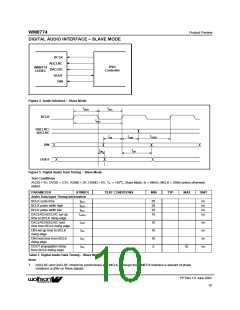
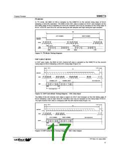
In Slave mode the WM8774 has a master detection circuit that automatically determines the
relationship between the master clock frequency and the sampling rate (to within +/- 32 system
clocks). If there is a greater than 32 clocks error the interface is disabled and maintains the output
level at the last sample. The master clock must be synchronised with ADCLRC/DACLRC, although
the WM8774 is tolerant of phase variations or jitter on this clock. Table 5 shows the typical master
clock frequency inputs for the WM8774.
The signal processing for the WM8774 typically operates at an oversampling rate of 128fs for both
ADC and DAC. The exception to this for the DAC is for operation with a 128 or 192fs system clock,
e.g. for 192kHz operation where the oversampling rate is 64fs. For ADC operation at 96kHz it is
recommended that the user set the ADCOSR bit. This changes the ADC signal processing
oversample rate to 64fs.
SAMPLING
RATE
System Clock Frequency (MHz)
128fs
192fs
256fs
384fs
512fs
768fs
(DACLRC/
ADCLRC)
DAC ONLY
32kHz
44.1kHz
48kHz
4.096
5.6448
6.144
6.144
8.467
8.192
11.2896
12.288
24.576
12.288
16.9340
18.432
36.864
16.384
22.5792
24.576
24.576
33.8688
36.864
9.216
96kHz
12.288
24.576
18.432
36.864
Unavailable Unavailable
192kHz
Unavailable Unavailable Unavailable Unavailable
Table 5 System Clock Frequencies Versus Sampling Rate
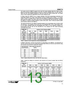
In Master mode BCLK, DACLRC and ADCLRC are generated by the WM8774. The frequencies of
ADCLRC and DACLRC are set by setting the required ratio of MCLK to DACLRC and ADCLRC using
the DACRATE and ADCRATE control bits (Table 6).
ADCRATE[2:0]/
DACRATE[2:0]
MCLK:ADCLRC/DACLRC
RATIO
000
001
010
011
100
101
128fs (DAC Only)
192fs (DAC Only)
256fs
384fs
512fs
768fs
Table 6 Master Mode MCLK:ADCLRC/DACLRC Ratio Select
Table 7 shows the settings for ADCRATE and DACRATE for common sample rates and MCLK
frequencies.
SAMPLING
RATE
System Clock Frequency (MHz)
128fs
192fs
256fs
384fs
512fs
768fs
(DACLRC/
ADCLRC)
DACRATE
=000
DACRATE
=001
ADCRATE/
DACRATE
=010
ADCRATE/
DACRATE
=011
ADCRATE/
DACRATE
=100
ADCRATE/
DACRATE
=101
32kHz
44.1kHz
48kHz
4.096
5.6448
6.144
6.144
8.467
8.192
11.2896
12.288
24.576
12.288
16.9340
18.432
36.864
16.384
22.5792
24.576
24.576
33.8688
36.864
9.216
96kHz
12.288
24.576
18.432
36.864
Unavailable Unavailable
192kHz
Unavailable Unavailable Unavailable Unavailable
Table 7 Master Mode ADC/DACLRC Frequency Selection
PP Rev 1.0 June 2002
13
ꢀꢀ

 WOLFSON [ WOLFSON MICROELECTRONICS PLC ]