Production Data
WM8352
REGISTER
ADDRESS
BIT
LABEL
DEFAULT
DESCRIPTION
REFER TO
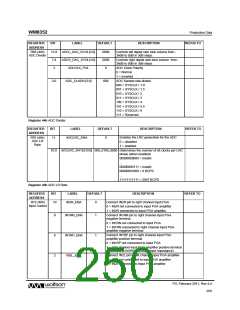
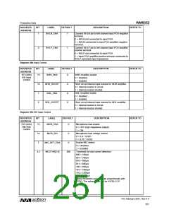
1
IN1LN_ENA
1
Connect IN1LN pin to left channel input PGA negative
terminal.
0 = IN1LN not connected to input PGA
1 = IN1LN connected to input PGA amplifier negative
terminal.
0
IN1LP_ENA
1
Connect IN1LP pin to left channel input PGA amplifier
positive terminal.
0 = IN1LP not connected to input PGA
1 = input PGA amplifier positive terminal connected to
IN1LP (constant input impedance)
Register 48h Input Control
REGISTER
ADDRESS
BIT
LABEL
DEFAULT
DESCRIPTION
REFER TO
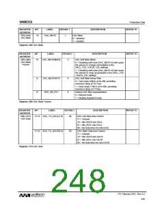
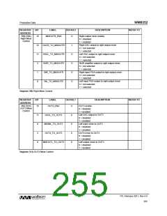
R73 (49h)
IN3 Input
Control
15
IN3R_ENA
0
IN3R Amplifier enable
0 = disabled
1 = enabled
14
7
IN3R_SHORT
IN3L_ENA
0
0
0
Short circuit internal input resistor for IN3R amplifier.
0 = Internal resistor in circuit.
1 = Internal resistor shorted.
IN3L Amplifier enable
0 = disabled
1 = enabled
6
IN3L_SHORT
Short circuit internal input resistor for IN3L amplifier.
0 = Internal resistor in circuit.
1 = Internal resistor shorted.
Register 49h IN3 Input Control
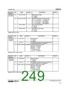
REGISTER
ADDRESS
BIT
LABEL
DEFAULT
DESCRIPTION
REFER TO
R74 (4Ah)
Mic Bias
Control
15
MICB_ENA
0
Microphone bias enable
0 = OFF (high impedance output)
1 = ON
14
7
MICB_SEL
MIC_DET_ENA
MCDTHR[2:0]
0
0
Microphone bias voltage control:
0 = 0.9 * AVDD
1 = 0.75 * AVDD
Enable MIC detect:
0 = Disabled
1 = Enabled
4:2
000
Threshold for bias current detection
000 = 160μA
001 = 330μA
010 = 500μA
011 = 680μA
100 = 850μA
101 = 1000μA
110 = 1200μA
111 = 1400μA
These threshold currents scale proportionally with
AVDD. The values given are for AVDD=3.3V.
PD, February 2011, Rev 4.4
251
w

 WOLFSON [ WOLFSON MICROELECTRONICS PLC ]