Production Data
WM8352
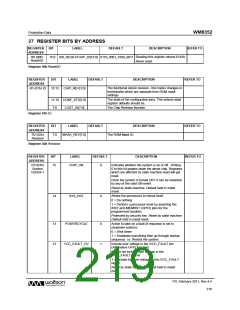
REGISTER
ADDRESS
BIT
LABEL
DEFAULT
DESCRIPTION
REFER TO
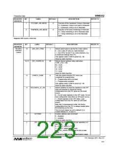
1
0
PCCOMP_HIB_MODE
0
Function of the Hysteresis Comp in hibernate.
0 = Hysteresis Comp is not used in hibernate
1 = Hysteresis Comp is on in hibernate
TEMPMON_HIB_MODE
0
Function of the temp monitoring in hibernate.
0 = Temp monitoring is off in hibernate state
1 = Temp monitoring is on in the hibernate
state
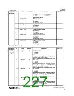
Register 05h System Hibernate
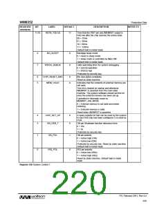
REGISTER
ADDRESS
BIT
LABEL
DEFAULT
DESCRIPTION
REFER TO
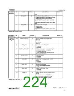
R6 (06h)
Interface
Control
15
USE_DEV_PINS
1
Selects which pins to use for the 2-wire control:
0 = Use 2-wire I/F pins as 2-wire interface
1 = Use GPIO 10 and 11 as 2-wire interface, e.g.
to download settings from PIC.
Only applies when CONFIG pins[1:0] = 00.
Reset by state machine.
14:13
DEV_ADDR[1:0]
00
Selects device address (only valid when
CONF_STS = 00)
00 = 0x34
01 = 0x36
10 = 0x3C
11 = 0x3E
Reset by state machine.
12
11
CONFIG_DONE
0
1
Tells the system that the PIC micro has
completed its programming.
0 = Programming still to be done
1 = Programming complete
Only applies when CONFIG pins[1:0] = 00.
Reset by state machine.
RECONFIG_AT_ON
Selects whether to reset the registers in the OFF
state and whether to reload the device
configuration from the PIC when an ON event
occurs.
0 = Do not reset registers in the OFF state. Do not
load configuration data when an ON event occurs.
1 = Reset registers in the OFF state. Load
configuration from the PIC when an ON event
occurs.
Note that, in development mode, the device
configuration from the PIC is always loaded when
first powering up the chip.
This bit must always be set to default (1) in
Custom Modes 01, 10 and 11.
9
3
AUTOINC
SPI_CFG
1
0
Enables address auto-increment
0 = disabled
1 = enabled
Reset by state machine.
Controls the SDOUT (GPIO6) pin operation in 4
wire mode
0 = SDOUT output is CMOS
1 = SDOUT output is open drain
Note: SPI_4WIRE must be set for this to take
effect.
Protected by security key. Default held in metal
PD, February 2011, Rev 4.4
223
w

 WOLFSON [ WOLFSON MICROELECTRONICS PLC ]