WM8352
Production Data
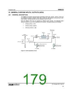
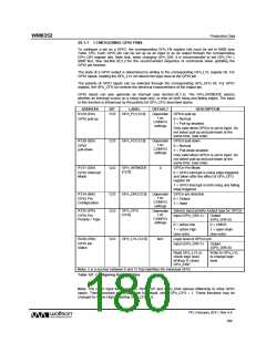
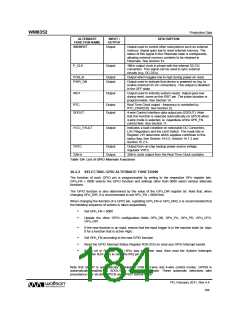
20.1.1 CONFIGURING GPIO PINS
To configure a pin as a GPIO, the corresponding GPn_FN register bits must be set to 0000 (see
Table 125). Each GPIO pin can be set up as an input or as an output through the corresponding
GPn_DIR register bits. Note that, when changing GPn_DIR, it is recommended to set GPn_FN =
0000 first. See Section 20.2.2 for the recommended sequence of commands when updating the
GPIO pin function.
The state of a GPIO output is determined by writing to the corresponding GPn_LVL register bit. For
GPIO inputs, reading the GPn_LVL bit returns the logic level at the GPIO pin.
The polarity of GPIO inputs can be selected through the corresponding GPn_CFG bit. For GPIO
outputs, the GPn_CFG bit controls the electrical characteristics of the output pin.
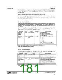
GPIO inputs can also generate an interrupt (see Section 20.1.3). The GPn_INTMODE selects
whether an interrupt occurs on a rising edge only, or else on both rising and falling edges. The input
to this function is influenced by the polarity bit GPn_CFG described above.
ADDRESS
R129 (81h)
BIT
LABEL
DEFAULT
DESCRIPTION
12:0
GPn_PU [12:0]
Dependan GPIOn pull-up
t on
GPIO pull-up
0 = Normal
CONFIG
settings
1 = Pull-up enabled
Only valid when GPIOn is set to input. Do
not select pull-up and pull-down at the
same time. (see note)
R130 (82h)
12:0
12:0
GPn_PD [12:0]
Dependan GPIOn pull-down
t on
GPIO
pull-down
0 = Normal
CONFIG
settings
1 = Pull-down enabled
Only valid when GPIOn is set to input. Do
not select pull-up and pull-down at the
same time. (see note)
R131 (83h)
GPn_INTMODE
0
GPIOn Pin Mode:
[12:0]
GPIO Interrupt
Mode
0 = GPIO interrupt is rising edge triggered
and taken after the effect of GPn_CFG
register bit
1 = GPIO interrupt is both rising and falling
edge triggered
R134 (86h)
12:0
12:0
GPn_DIR [12:0]
Dependan GPIOn pin direction
t on
CONFIG
settings
GPIO Pin
Configuration
0 = Output
1 = Input
R135 (87h)
GPn_CFG
Dependan Selects input polarity /output type for GPIOn
[12:0]
t on
CONFIG
settings
GPIO Pin
Polarity / Type
Input (GPn_DIR=1)
Output
(GPn_DIR=0)
0 = active low
1 = active high
(see note)
0 = CMOS
1 = open-drain
(see note)
R230 (E6h)
12:0
GPn_LVL [12:0]
N/A
Logic level of GPIOn pin
GPIO pin
status
Input (GPn_DIR=1)
Output
(GPn_DIR=0)
Read GPn_LVL to
check logic level.
Writing ‘0’ clears
GPn_EINT
Write to GPn_LVL
to change logic
level.
Note: n is a number between 0 and 12 that identifies the individual GPIO.
Table 121 Configuring the GPIO Pins
Note: The GPIO input functions /MR, /WAKEUP and /LDO_ENA behave differently to other GPIO
inputs. These functions are Active Low by default, when GPn_CFG = 1. These functions may be
changed to Active High by setting GPn_CFG = 0.
PD, February 2011, Rev 4.4
180
w

 WOLFSON [ WOLFSON MICROELECTRONICS PLC ]