Production Data
WM8352
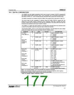
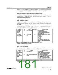
19.6 DIGITAL COMPARATORS
The WM8352 has four digital comparators which may be used to compare AUXADC measurement
data against programmable threshold values. Each comparator has an associated interrupt flag, as
described in Section 19.7, which indicates that the associated data is beyond the threshold value.
The digital comparators are enabled using the DCMPn_ENA register bits as described in Table 119.
The source data for each comparator is selected using the DCMPn_SRCSEL register bits; this
selects one of the eight AUXADC channels for each comparator. Note that, if required, the same
AUXADC channel may be selected for more than one comparator; this would allow more than one
threshold to be monitored on the same AUXADC channel.
The DCMPn_GT register bits select whether an interrupt will be indicated when the measured value
is above the threshold or when the measured value is below the threshold.
The threshold DCMPn_THR is a 12-bit code for each comparator. This field follows the same voltage
scaling and voltage reference as the associated AUXADC channel source.
ADDRESS
R12 (0Ch)
BIT
LABEL
DEFAULT
DESCRIPTION
Digital comparator 4 enable
0 = disabled
3
DCMP4_ENA
0
Power Mgmt (5)
1 = enabled
or
2
1
DCMP3_ENA
DCMP2_ENA
DCMP1_ENA
0
0
Digital comparator 3 enable
0 = disabled
R163 (A3h)
Generic
Comparator
Control
1 = enabled
Digital comparator 2 enable
0 = disabled
1 = enabled
0
0
Digital comparator 1 enable
0 = disabled
1 = enabled
R164 (A4h)
Generic
comparator 1
15:13
DCMPn_SRCS
EL [2:0]
000
DCOMPn source select.
000 = AUX1
001 = AUX2
010 = AUX3
R165 (A5h)
Generic
Comparator 2
011 = AUX4
100 = USB
101 = LINE
110 = BATT
R166 (A6h)
Generic
111 = TEMP
Comparator 3
DCMPn_GT
DCOMPn interrupt control
12
0
0 = interrupt when the source is
less than threshold
R167 (A7h)
Generic
Comparator 4
1 = interrupt when the source is
greater than threshold
11:0
DCMPn_THR
000h
DCOMPn threshold
[11:0]
(12-bit unsigned binary number)
Note: n is a number between 1 and 4 that identifies the individual comparator
Note: The Comparator Enable bits can each be accessed through two separate control registers.
Reading from or writing to either register location has the same effect.
Table 119 AUXADC Digital Comparator Control
PD, February 2011, Rev 4.4
177
w

 WOLFSON [ WOLFSON MICROELECTRONICS PLC ]