WM8352
Production Data
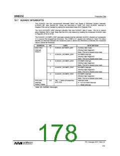
19.7 AUXADC INTERRUPTS
The AUXADC has five second-level interrupts which can trigger a first-level System Interrupt,
AUXADC_INT (see Section 24). These are described in Table 120. Each AUXADC interrupt in
Register R26 can be masked by setting the associated mask bit in Register R34.
The AUX_DATARDY_EINT interrupt indicates that new AUXADC data is ready. This bit is cleared
when Register R26 is read. Note that this bit is not cleared by reading the measured AUXADC data
in Registers R152 to R159.
The AUXADC_DCOMPn_EINT interrupts indicate that the selected AUXADC channel on Comparator
‘n’ is beyond the programmed threshold. The DCMPn_GT register bits defined in Table 119 select
whether an interrupt indicates the measured value is above the threshold or indicates the measured
value is below the threshold.
ADDRESS
BIT
LABEL
DESCRIPTION
Auxiliary data ready.
R26 (1Ah)
8
AUXADC_DATARDY_EINT
Interrupt
Status 2
(Rising Edge triggered)
Note: This bit is cleared once read.
DCOMP4 interrupt.
7
6
AUXADC_DCOMP4_EINT
AUXADC_DCOMP3_EINT
AUXADC_DCOMP2_EINT
AUXADC_DCOMP1_EINT
(Rising Edge triggered)
Note: This bit is cleared once read.
DCOMP3 interrupt.
(Rising Edge triggered)
Note: This bit is cleared once read.
DCOMP2 interrupt.
5
(Rising Edge triggered)
Note: This bit is cleared once read.
DCOMP1 interrupt.
4
(Rising Edge triggered)
Note: This bit is cleared once read.
Interrupt mask.
R34 (22h)
8:4
“IM_” + name of respective
bit in R26
Interrupt
Status 2 Mask
0 = Do not mask interrupt.
1 = Mask interrupt.
Table 120 AUXADC Interrupts
PD, February 2011, Rev 4.4
178
w

 WOLFSON [ WOLFSON MICROELECTRONICS PLC ]