W9412G6JH
10.6 Table 6: Output Slew Rate Matching Ratio Characteristics
SLEW RATE CHARACTERISTIC
PARAMETER
DDR500
DDR400
DDR333
NOTES
MIN.
0.67
MAX.
MIN.
0.67
MAX.
MIN.
MAX.
Output Slew Rate Matching Ratio
(Pullup to Pulldown)
1.5
1.5
0.67
1.5
e, m
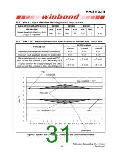
10.7 Table 7: AC Overshoot/Undershoot Specification for Address and Control Pins
SPECIFICATION
PARAMETER
DDR500
DDR400
DDR333
1.5 V
Maximum peak amplitude allowed for overshoot
Maximum peak amplitude allowed for undershoot
1.5 V
1.5 V
1.5 V
1.5 V
1.5 V
The area between the overshoot signal and VDD
must be less than or equal to Max. area in Figure 3
4.5 V-nS
4.5 V-nS
4.5 V-nS
4.5 V-nS
4.5 V-nS
4.5 V-nS
The area between the undershoot signal and GND
must be less than or equal to Max. area in Figure 3
VDD
Overshoot
5
Max. amplitude = 1.5V
4
3
2
Max. area
1
0
-1
-2
Max. amplitude = 1.5V
-3
GND
-4
-5
0 0.5 0.68751.0 1.5 2.0 2.5 3.0 3.5 4.0 4.5 5.0 5.5 6.06.3125 6.5 7.0
Time (nS)
Undershoot
Figure 3: Address and Control AC Overshoot and Undershoot Definition
Publication Release Date: Nov. 29, 2011
- 31 -
Revision A03

 WINBOND [ WINBOND ]