W9412G6JH
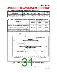
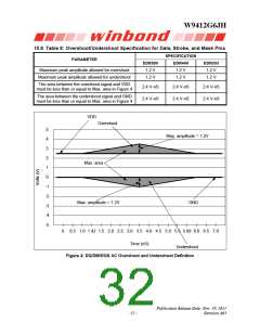
10.8 Table 8: Overshoot/Undershoot Specification for Data, Strobe, and Mask Pins
SPECIFICATION
PARAMETER
DDR500
DDR400
DDR333
1.2 V
Maximum peak amplitude allowed for overshoot
Maximum peak amplitude allowed for undershoot
1.2 V
1.2 V
1.2 V
1.2 V
1.2 V
The area between the overshoot signal and VDD
must be less than or equal to Max. area in Figure 4
2.4 V-nS
2.4 V-nS
2.4 V-nS
2.4 V-nS
2.4 V-nS
2.4 V-nS
The area between the undershoot signal and GND
must be less than or equal to Max. area in Figure 4
VDD
Overshoot
5
Max. amplitude = 1.2V
4
3
2
Max. area
1
0
-1
-2
Max. amplitude = 1.2V
-3
GND
-4
-5
0
0.5 1.0 1.42 1.5 2.0 2.5 3.0 3.5 4.0 4.5 5.0 5.5 5.68 6.0 6.5 7.0
Time (nS)
Undershoot
Figure 4: DQ/DM/DQS AC Overshoot and Undershoot Definition
Publication Release Date: Nov. 29, 2011
- 32 -
Revision A03

 WINBOND [ WINBOND ]