W90N745CD/W90N745CDG
Continued
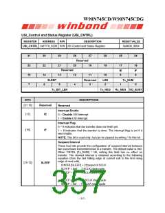
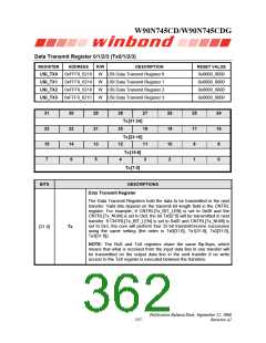
BITS
DESCRIPTIONS
[11]
Reserved
LSB
Reserved
Send LSB First
0 = The MSB is transmitted/received first (which bit in TxX/RxX
register that is depends on the Tx_BIT_LEN field in the CNTRL
register).
[10]
1 = The LSB is sent first on the line (bit TxX[0]), and the first bit
received from the line will be put in the LSB position in the Rx register
(bit RxX[0]).
Transmit/Receive Numbers
This field specifies how many transmit/receive numbers should be
executed in one transfer.
00 = Only one transmit/receive will be executed in one transfer.
[9:8]
Tx_NUM
01 = Two successive transmit/receive will be executed in one transfer.
10 = Three successive transmit/receive will be executed in one
transfer.
11 = Four successive transmit/receive will be executed in one transfer.
Transmit Bit Length
This field specifies how many bits are transmitted in one
transmit/receive. Up to 32 bits can be transmitted.
Tx_BIT_LEN = 0x01 … 1 bit
Tx_BIT_LEN = 0x02 … 2 bits
……
[7:3]
Tx_BIT_LEN
Tx_BIT_LEN = 0x1f … 31 bits
Tx_BIT_LEN = 0x00 … 32 bits
Transmit On Negative Edge
0 = The mw_so_o signal is changed on the rising edge of mw_sclk_o.
[2]
[1]
Tx_NEG
Rx_NEG
1 = The mw_so_o signal is changed on the falling edge of
mw_sclk_o.
Receive On Negative Edge
0 = The mw_si_i signal is latched on the rising edge of mw_sclk_o.
1 = The mw_si_i signal is latched on the falling edge of mw_sclk_o.
Go and Busy Status
0 = Writing 0 to this bit has no effect.
1 = Writing 1 to this bit starts the transfer. This bit remains set during
the transfer and is automatically cleared after transfer finished.
[0]
GO_BUSY
NOTE: All registers should be set before writing 1 to the GO_BUSY bit
in the CNTRL register. When a transfer is in progress, writing to any
register of the USI(Microwire/SPI) master core has no effect.
Publication Release Date: September 22, 2006
- 353 -
Revision A2

 WINBOND [ WINBOND ]