W90N745CD/W90N745CDG
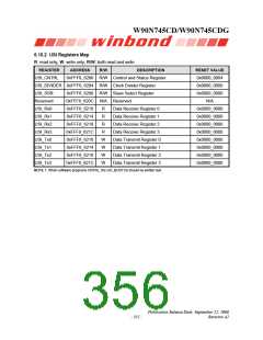
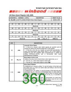
USI Slave Select Register (USI_SSR)
REGISTER
USI_SSR
ADDRESS
R/W
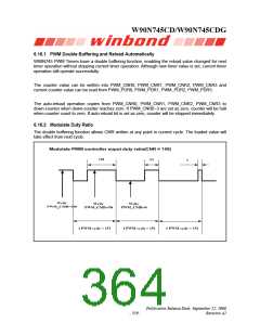
DESCRIPTION
RESET VALUE
0xFFF8_6208 R/W USI Slave Select Register
0x0000_0000
31
23
15
7
30
22
14
6
29
21
13
5
28
20
12
4
27
19
11
3
26
18
10
25
17
9
24
16
8
Reserved
Reserved
Reserved
2
1
0
Reserved
ASS
SS_LVL
SSR[1:0]
BITS
DESCRIPTIONS
Automatic Slave Select
0 = If this bit is cleared, slave select signals are asserted and de-
asserted by setting and clearing related bits in SSR register.
1 = If this bit is set, mw_ss_o signals are generated automatically. It
means that device/slave select signal, which is set in SSR register is
asserted by the USI controller when transmit/receive is started by
setting CNTRL[GO_BUSY], and is de-asserted after every
transmit/receive is finished.
[3]
ASS
Slave Select Active Level
It defines the active level of device/slave select signal (mw_ss_o).
0 = The mw_ss_o slave select signal is active Low.
1 = The mw_ss_o slave select signal is active High.
[2]
SS_LVL
Slave Select Register
If SSR[ASS] bit is cleared, writing 1 to any bit location of this field sets
the proper mw_ss_o line to an active state and writing 0 sets the line
back to inactive state.
If SSR[ASS] bit is set, writing 1 to any bit location of this field will select
appropriate mw_ss_o line to be automatically driven to active state for
the duration of the transmit/receive, and will be driven to inactive state
for the rest of the time. (The active level of mw_ss_o is specified in
SSR[SS_LVL]).
[1:0]
SSR
NOTE: This interface can only drive one device/slave at a given time.
Therefore, the slave select of the selected device must be set to its
active level before starting any read or write transfer.
Publication Release Date: September 22, 2006
- 355 -
Revision A2

 WINBOND [ WINBOND ]