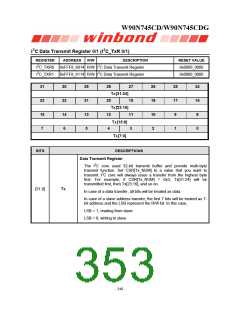
W90N745CD/W90N745CDG
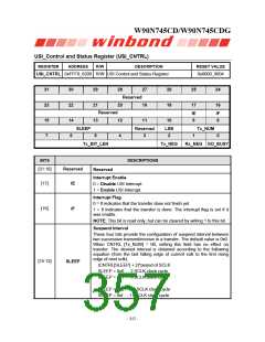
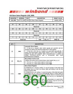
USI_Control and Status Register (USI_CNTRL)
REGISTER
ADDRESS
R/W
DESCRIPTION
RESET VALUE
0xFFF8_6200 R/W USI Control and Status Register
0x0000_0004
USI_CNTRL
31
23
15
7
30
22
14
6
29
21
13
5
28
20
12
4
27
19
11
26
18
10
25
17
24
16
Reserved
Reserved
IE
9
IF
8
SLEEP
Reserved
3
LSB
2
Tx_NUM
0
1
Tx_BIT_LEN
Tx_NEG
Rx_NEG GO_BUSY
BITS
DESCRIPTIONS
[31:18]
Reserved
IE
Reserved
Interrupt Enable
[17]
[16]
0 = Disable USI Interrupt.
1 = Enable USI Interrupt.
Interrupt Flag
0 = It indicates that the transfer dose not finish yet.
IF
1 = It indicates that the transfer is done. The interrupt flag is set if it
was enable.
NOTE: This bit is read only, but can be cleared by writing 1 to this bit.
Suspend Interval
These four bits provide the configuration of suspend interval between
two successive transmit/receive in a transfer. The default value is 0x0.
When CNTRL [Tx_NUM] = 00, setting this field has no effect on
transfer. The desired interval is obtained according to the following
equation (from the last falling edge of current sclk to the first rising
edge of next sclk):
[15:12]
SLEEP
(CNTRL[SLEEP] + 2)*period of SCLK
SLEEP = 0x0 … 2 SCLK clock cycle
SLEEP = 0x1 … 3 SCLK clock cycle
……
SLEEP = 0xe … 16 SCLK clock cycle
SLEEP = 0xf … 17 SCLK clock cycle
- 352 -

 WINBOND [ WINBOND ]