W90N745CD/W90N745CDG
31
23
15
30
22
14
29
21
13
28
Reserved
20
Reserved
12
Reserved
27
19
11
26
18
10
25
17
9
24
16
8
7
6
5
4
3
2
1
0
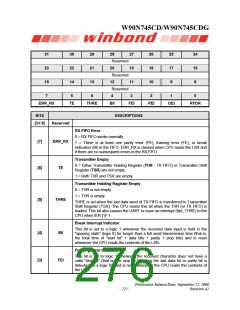
ERR_RX
TE
THRE
BII
FEI
PEI
OEI
RFDR
BITS
DESCRIPTIONS
-
[31:8]
Reserved
ERR_RX
RX FIFO Error
0 = RX FIFO works normally
[7]
1 = There is at least one parity error (PE), framing error (FE), or break
indication (BI) in the FIFO. ERR_RX is cleared when CPU reads the LSR and
if there are no subsequent errors in the RX FIFO.
Transmitter Empty
0 = Either Transmitter Holding Register (THR - TX FIFO) or Transmitter Shift
Register (TSR) are not empty.
[6]
[5]
TE
1 = Both THR and TSR are empty.
Transmitter Holding Register Empty
0 = THR is not empty.
1 = THR is empty.
THRE
THRE is set when the last data word of TX FIFO is transferred to Transmitter
Shift Register (TSR). The CPU resets this bit when the THR (or TX FIFO) is
loaded. This bit also causes the UART to issue an interrupt (Irpt_THRE) to the
CPU when IER [1]=1.
Break Interrupt Indicator
This bit is set to a logic 1 whenever the received data input is held in the
"spacing state" (logic 0) for longer than a full word transmission time (that is,
the total time of "start bit" + data bits + parity + stop bits) and is reset
whenever the CPU reads the contents of the LSR.
[4]
[3]
BII
Framing Error Indicator
This bit is set to logic 1 whenever the received character does not have a
valid "stop bit" (that is, the stop bit following the last data bit or parity bit is
detected as a logic 0), and is reset whenever the CPU reads the contents of
the LSR.
FEI
Publication Release Date: September 22, 2006
- 271 -
Revision A2

 WINBOND [ WINBOND ]