W90N745CD/W90N745CDG
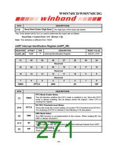
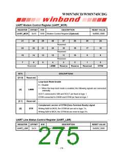
UART Modem Control Register (UART_MCR)
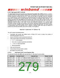
REGISTER OFFSET R/W
DESCRIPTION
RESET VALUE
UART_MCR
0x10
30
22
14
6
R/W Modem Control Register (Optional)
0x0000_0000
31
23
15
7
29
21
13
5
28
20
12
27
Reserved
19
26
18
10
25
17
9
24
16
8
Reserved
11
Reserved
3
4
2
1
0
Reserved
Reserved
LBME
LBME
Reserve
Reserve
Reserved
DTR#
BITS
DESCRIPTIONS
-
[31:5]
Loop-back Mode Enable
0 = Disable
1 = When the loop-back mode is enabled, the following signals are connected
internally
[4]
SOUT connected to SIN and SOUT pin fixed at logic 1
DTR# connected to DSR# and DTR# pin fixed at logic 1
[3:1]
[0]
Reserved
DTR
-
Complement version of DTR# (Data-Terminal-Ready) signal
Writing 0x00 to MCR, the DTR# bit are set to logic 1’s;
Writing 0x0f to MCR, the DTR# bit are reset to logic 0’s.
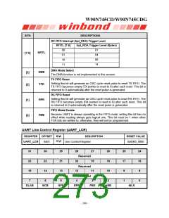
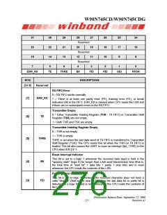
UART Line Status Control Register (UART_LSR)
REGISTER
OFFSET
R/W
DESCRIPTION
Line Status Register
RESET VALUE
UART_LSR
0x14
R
0x6060_6060
- 270 -

 WINBOND [ WINBOND ]