WED3DL644V
White Electronic Designs
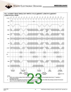
FIG. 14 BURST READ SINGLE BIT WRITE CYCLE @BURST LENGTH=2 @BURST
LENGTH=FULL PAGE
0
1
2
3
4
5
6
7
8
9
10
11
12
13
14
15
16
17
18
19
CLOCK
Note 1
HIGH
CKE
CE#
RAS#
Note 2
CAS#
ADDR
RAa
CAa
RBb
CAb
RAc
CAd
CBc
BA
RAa
A10/AP
RBb
RAc
CL = 2
DQ
DAa0
DAa0
QAb0 QAb1
DBc0
DBc0
QAd0 QAd1
CL = 3
QAb0 QAb1
QAd0 QAd1
WE#
DQM
Row Active
(A-Bank)
Row Active
(B-Bank)
Row Active
(A-Bank)
Read
(A-Bank)
Precharge
(Both Banks)
Write
Read with
Write with
Auto Precharge
(B-Bank)
(A-Bank) Auto Precharge
(A-Bank)
DON'T CARE
NOTES:
1.
BRSW mode is enabled by setting A9 “High” at MRS (Mode Register Set). At the BRSW Mode, the burst length at write is fixed to “1” regardless of
programmed burst length.
2.
When BRSW write command with auto precharge is executed, keep it in mind that tRAS should not be violated. Auto precharge is executed at the burst-end
cycle, so in the case of BRSW write command, the next cycle starts the precharge.
August 2005
Rev. 6
23
White Electronic Designs Corporation • (602) 437-1520 • www.wedc.com

 WEDC [ WHITE ELECTRONIC DESIGNS CORPORATION ]