VSC8601 Datasheet
Configuration
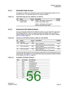
Table 37.
Available LED Mode Settings (continued)
Mode
11
Bit Setting LED Indicates
Reserved
12
1100
Autoneg_Fault
13
Reserved
1110
14
Force LED off
Force LED on
15
1111
4.3.3
Enhanced LED Behavior
The following table lists the settings available.
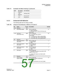
Enhanced LED Behavior, Address 17E (0x11)
Table 38.
Bit
Name
Access Description
Default
15:13 Reserved
RO
12
LED pulsing enable
R/W
This is a sticky bit.
0 = Normal operation.
0
1 = LEDs pulse with a 5 KHz, 20% duty cycle
when active.
11:10 LED blink /
R/W
This is a sticky bit.
01
pulse-stretch rate
00 = 2.5 Hz blink rate / 400 ms
pulse-stretch.
01 = 5 Hz blink rate / 200 ms pulse-stretch.
10 = 10 Hz blink rate / 100 ms pulse-stretch.
11 = 20 Hz blink rate / 50 ms pulse-stretch.
9:8
7
Reserved
RO
LED2 pulse-stretch /
blink select
R/W
This is a sticky bit.
1 = Pulse-stretch.
0 = Blink.
1
1
1
0
6
5
4
LED1 pulse-stretch /
blink select
R/W
R/W
R/W
This is a sticky bit.
1 = Pulse-stretch.
0 = Blink.
LED0 pulse-stretch /
blink select
This is a sticky bit.
1 = Pulse-stretch.
0 = Blink.
LED mode
This is a sticky bit.
1 = Enhanced LED method (controlled by MII
register 16E and 17E).
0 = Simple LED method (controlled by MII
register 27).
3
2
Reserved
RO
LED2 combine
feature disable
R/W
This is a sticky bit.
0 = Combine enabled (Link/Activity,
Duplex/Collision).
0
1 = Disable Combination (Link only, Duplex
only).
Revision 4.1
September 2009
Page 57

 VITESSE [ VITESSE SEMICONDUCTOR CORPORATION ]