VSC8601 Datasheet
Configuration
Table 44.
Extended PHY Control 4, Address 23E (0x17) (continued)
Bit
Name
Access Description
RO This is a self-clearing bit.
Default
7:0
CRC error counter
0x00
CRC error counter for the Ethernet packet
generator. The value saturates at 0xFF
and subsequently clears when read and
restarts count.
Note Bits 9:8 are only valid if bit 10 is set.
4.3.10
Reserved Extended Registers
The bits in the extended register page space at addresses 24E, 25E, and 26E (0x18,
0x19, and 0x1A, respectively) are reserved.
4.3.11
Extended PHY Control 5
The following table lists the settings available.
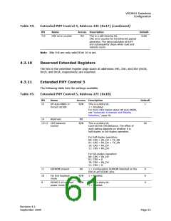
Extended PHY Control 5, Address 27E (0x1B)
Table 45.
Bit
Name
Access Description
Default
15
HP Auto-MDIX in
forced 10/100
R/W
This is a sticky bit.
1 = Disabled.
1
For more information about HP Auto-MDIX,
see “Automatic Crossover and Polarity
Detection,” page 20.
14
Reserved
RO
13:12 CRS behavior
control
R/W
This is a sticky bit.
00
Controls the CRS Behavior. The effect of
each setting depends on whether it is
half-duplex or full-duplex operation.
For half-duplex operation:
00: CRS = RX_DV + TX_EN
01: CRS = RX_DV + TX_EN
10: CRS = RX_DV
11: CRS = RX_DV.
For full-duplex operation:
00: CRS = RX_DV
01: CRS = 0
10: CRS = RX_DV
11: CRS = 0.
11
10
9
EEPROM present
RO
1 = Configuration EEPROM detected on the
EECLK and EEDAT pins.
0
0
0
Far End loopback
mode
R/W
R/W
1 = Enabled.
PICMG 2.16 reduced
power mode
This is a sticky bit.
1 = Enabled.
Revision 4.1
September 2009
Page 61

 VITESSE [ VITESSE SEMICONDUCTOR CORPORATION ]