VSC8601 Datasheet
Configuration
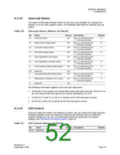
4.3.1
Extended Page Access
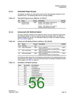
The register at address 31 controls the access to the extended page registers for the
VSC8601 device. The following table lists the settings available.
Table 35.
Extended Page Access, Address 31 (0x1F)
Bit
Name
Access Description
R/W 0x0000 = MII register 16 through 30
Default
15:0 Extended page
register access
0x0000
accesses main register space
0x0001 = MII register 16 through 30
accesses extended register space
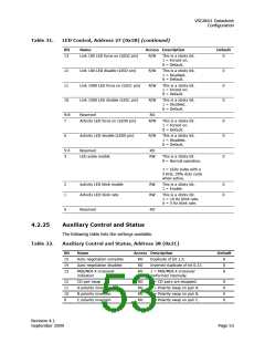
4.3.2
Enhanced LED Method Select
If you are using the enhanced LED method of control, you can control the LEDs using
the following settings. If you are using the simple LED method, there are different
register settings you can use. For information about the simple LED register settings,
see “LED Control,” page 52.
Table 36.
Enhanced LED Method Select, Address 16E (0x10)
Bit
Name
Access Description
Default
15:12 Reserved
RO
11:8
7:4
LED2 mode select
R/W
R/W
R/W
This is a sticky bit.
Select from LED modes 0-15 listed below.
0010
0001
1010
LED1 mode select
LED0 mode select
This is a sticky bit.
Select from LED modes 0-15 listed below.
3:0
This is a sticky bit.
Select from LED modes 0-15 listed below.
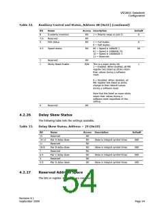
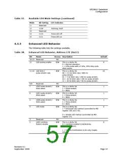
The following table shows the LED functional modes that can be programmed into any
of the device’s LED outputs. For more information about accessing or reading the status
of the outputs, see Table 36, page 56.
Table 37.
Available LED Mode Settings
Mode
Bit Setting LED Indicates
0
1
2
3
4
5
6
7
8
9
10
0000
0001
0010
0011
0100
0101
0110
0111
1000
1001
1010
Link/Activity
Link1000/Activity
Link100/Activity
Link10/Activity
Link100/1000/Activity
Link10/1000/Activity
Link10/100/Activity
Reserved
Duplex/Collision
Collision
Activity
Revision 4.1
September 2009
Page 56

 VITESSE [ VITESSE SEMICONDUCTOR CORPORATION ]