VSC8601 Datasheet
Configuration
4.2.23
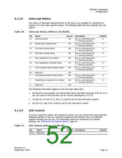
Interrupt Status
The status of interrupts already written to the device are available for reading from
register 26 in the main registers space. The following table lists the readouts you can
expect.
Table 30.
Interrupt Status, Address 26 (0x1A)
Bit
Name
Access Description
Default
15
Interrupt status
RO
RO
RO
RO
RO
RO
RO
This is a self-clearing bit.
1 = Interrupt pending.
0
14
13
12
11
10
9
Speed state change status
Link state change status
This is a self-clearing bit.
1 = Interrupt pending.
0
0
0
This is a self-clearing bit.
1 = Interrupt pending.
FDX state change status
This is a self-clearing bit.
1 = Interrupt pending.
Auto-negotiation error status
Auto-negotiation complete status
Inline powered device detect status
This is a self-clearing bit.
1 = Interrupt pending.
This is a self-clearing bit.
1 = Interrupt pending.
0
0
This is a self-clearing bit.
1 = Interrupt pending.
8:3
2
Reserved
RO
RO
Link speed downshift detect status
This is a self-clearing bit.
1 = Interrupt pending.
0
0
1
0
Master/Slave resolution error status
Reserved
RO
RO
This is a self-clearing bit.
1 = Interrupt pending.
The following information applies to the interrupt status bits:
•
All set bits in this register are cleared after being read (self-clearing). If bit 26.15 is
set, the cause of the interrupt can be read by reading bits 26.14:0.
•
•
For bits 26.14 and 26.12, bit 0.12 must be set for this interrupt to assert.
For bit 26.2, bits 4.8:5 must be set for this interrupt to assert.
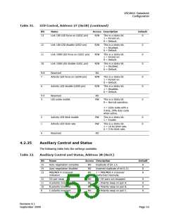
4.2.24
LED Control
If you are using the simple LED method of control, you can control the LEDs using the
following settings. If you are using the enhanced LED method, there are different
register settings you can use. For information about the enhanced LED register
settings, see “Enhanced LED Method Select,” page 56.
Table 31.
LED Control, Address 27 (0x1B)
Bit
Name
Access Description
Default
15:14
Reserved
RO
Revision 4.1
September 2009
Page 52

 VITESSE [ VITESSE SEMICONDUCTOR CORPORATION ]