VSC8601 Datasheet
Configuration
Note If bit 1 is set to 1 in this register, automatic exchange of next pages is disabled,
and control is returned to the user through the SMI after the base page is exchanged.
The user then must send the correct sequence of next pages to the link partner,
determine the common capabilities, and force the device into the correct configuration
following the successful exchange of pages.
4.2.16
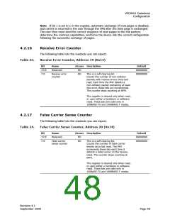
Receive Error Counter
The following table lists the readouts you can expect.
Receive Error Counter, Address 19 (0x13)
Table 23.
Bit
Name
Access Description
Default
00000000
00000000
15:8
7:0
Reserved
RO
Receive error
counter
RO
This is a self-clearing bit.
Counts the number of non-collision
packets with receive errors since last
read. Each time the PHY detects a
non-collision packet containing at least
one error, these bits are incremented.
The counter stops counting at 0FFh.
This register is cleared only when read,
or upon either a hardware or software
reset. These bits are valid only in
100BASE-TX and 1000BASE-T modes.
4.2.17
False Carrier Sense Counter
The following table lists the readouts you can expect.
False Carrier Sense Counter, Address 20 (0x14)
Table 24.
Bit
Name
Access Description
Default
00000000
00000000
15:8
7:0
Reserved
RO
False carrier
RO
This is a self-clearing bit.
sense counter
Counts the number of false carrier
events since last read. The PHY
increments these bits each time it
detects a false carrier on the receive
input. The counter stops counting at
0FFh.
This register is cleared only when read,
or upon either a hardware or software
reset. These bits are valid only in
100BASE-TX and 1000BASE-T modes.
Revision 4.1
September 2009
Page 48

 VITESSE [ VITESSE SEMICONDUCTOR CORPORATION ]