VSC8601 Datasheet
Configuration
•
When bits 11:0 are set to 00, the squelch threshold levels are based on the IEEE
standard for 10BASE-T. When set to 01, the squelch level is decreased, which may
improve the bit error rate performance on long loops. When set to 10, the squelch
level is increased and may improve the bit error rate in high-noise environments.
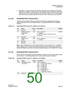
4.2.20
Extended PHY Control Set 1
The bits in the extended control set control the MAC auto-negotiation functioning,
SGMII alignment errors, and EEPROM status. The following table lists the available
settings.
Table 27.
Extended PHY Control 1, Address 23 (0x17)
Bit
15:9
8
Name
Access Description
Default
Reserved
RO
RGMII skew timing
compensation
enable
R/W
This is a sticky bit.
CMODE
0 = Disabled.
1 = Adds 2 ns delay to the RX_CLK and
TX_CLK pins.
7:6
5
Reserved
RO
ActiPHY mode
enable
R/W
This is a sticky bit.
1 = Enabled.
CMODE
4:1
0
Reserved
Reserved
RO
RO
Note After configuring bit 12 of the extended PHY control register set 1, a software
reset (register 0, bit 15) must be written to change the device operating mode. Bit 1
allows for flexibility in printed circuit board layouts because it can reorder the TXD pins.
4.2.21
Extended PHY Control Set 2
The second set of extended controls is located in register 24 in the main register space
for the device. The following table lists the settings and readouts available.
Table 28.
Extended PHY Control 2, Address 24 (0x18)
Bit
Name
Access Description
R/W This is a sticky bit.
Default
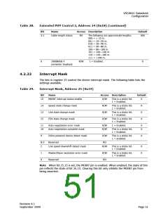
15:13
100BASE-TX edge
rate control
110
011 = +5 Edge rate (slowest).
010 = +4 Edge rate.
001 = +3 Edge rate.
000 = +2 Edge rate.
111 = +1 Edge rate.
110 = Default edge rate.
101 = –1 Edge rate.
100 = –2 Edge rate (fastest).
12:4
Reserved
RO
Revision 4.1
September 2009
Page 50

 VITESSE [ VITESSE SEMICONDUCTOR CORPORATION ]