VSC8601 Datasheet
Configuration
4.2.18
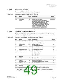
Disconnect Counter
The following table lists the readouts you can expect.
Disconnect Counter, Address 21 (0x15)
Table 25.
Bit
Name
Access Description
Default
00000000
00000000
15:8
7:0
Reserved
RO
Disconnect
counter
RO
This is a self-clearing bit.
Counts the number of non-collision
packets with receive errors after the last
read. The PHY increments these bits
each time the Carrier Integrity Monitor
(CIM) enters the link unstable state. The
counter stops counting at 0FFh. This
register is cleared only when read or
upon a hardware or software reset.
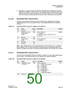
4.2.19
Extended Control and Status
The bits in register 22 provide additional device control and readouts. The following
table lists the settings available.
Table 26.
Extended Control and Status, Address 22 (0x16)
Bit
Name
Access Description
Default
15
Force 10BASE-T
link high
R/W
This is a sticky bit.
1 = Bypass link integrity test.
0 = Enable link integrity test.
0
14
13
Jabber detect
disable
R/W
R/W
This is a sticky bit.
1 = Disable jabber detect.
0
1
Disable 10BASE-T
echo
This is a sticky bit.
1 = Disable 10BASE-T echo.
12
SQE disable mode
R/W
R/W
1 = Disable SQE transmit.
1
11:10
10BASE-T squelch
control
This is a sticky bit.
00 = Normal squelch.
01 = Low squelch.
10 = High squelch.
11 = Reserved.
00
9
8
Reserved
EOF Error
RO
RO
RO
RO
This bit is self-clearing.
1 = EOF error detected.
0
0
0
7
10BASE-T
disconnect state
This bit is self-clearing.
1 = 10BASE-T link disconnect detected.
6
10BASE-T link
status
1 = 10BASE-T link active.
5:0
Reserved
The following information applies to the extended control and status bits:
•
When bit 15 is set, the link integrity state machine is bypassed and the PHY is
forced into a link pass status.
Revision 4.1
September 2009
Page 49

 VITESSE [ VITESSE SEMICONDUCTOR CORPORATION ]