VSC8601 Datasheet
Configuration
Table 28.
Extended PHY Control 2, Address 24 (0x18) (continued)
Bit
Name
Access Description
Default
3:1
Cable length status
RO
The following are approximate lengths:
000
000 = < 10 m.
001 = 10—20 m.
010 = 20—40 m.
011 = 40—80 m.
100 = 80—100 m.
101 = 100—140 m.
110 = 140—180 m.
111 = >180 m.
0
1000BASE-T
R/W
1 = Enabled.
0
connector loopback
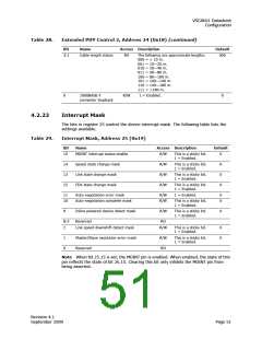
4.2.22
Interrupt Mask
The bits in register 25 control the device interrupt mask. The following table lists the
settings available.
Table 29.
Interrupt Mask, Address 25 (0x19)
Bit
Name
Access Description
Default
15
MDINT interrupt status enable
R/W
R/W
R/W
R/W
This is a sticky bit.
1 = Enabled.
0
14
13
12
Speed state change mask
Link state change mask
FDX state change mask
This is a sticky bit.
1 = Enabled.
0
0
0
This is a sticky bit.
1 = Enabled.
This is a sticky bit.
1 = Enabled.
11
10
Auto-negotiation error mask
R/W
R/W
1 = Enabled.
0
0
Auto-negotiation complete mask
This is a sticky bit.
1 = Enabled.
9
Inline powered device detect mask
R/W
This is a sticky bit.
1 = Enabled.
0
8:3
2
Reserved
RO
Link speed downshift detect mask
R/W
This is a sticky bit.
1 = Enabled.
0
0
1
0
Master/Slave resolution error mask
Reserved
R/W
RO
This is a sticky bit.
1 = Enabled.
Note When bit 25.15 is set, the MDINT pin is enabled. When enabled, the state of this
pin reflects the state of bit 26.15. Clearing this bit only inhibits the MDINT pin from
being asserted.
Revision 4.1
September 2009
Page 51

 VITESSE [ VITESSE SEMICONDUCTOR CORPORATION ]