VSC8601 Datasheet
Configuration
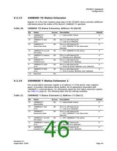
4.2.8
Auto-Negotiation Link Partner Next Page Receive
The bits in register 8 of the main register space work together with register 7 to
determine certain aspects of the LP auto-negotiation. The following table lists the
possible readouts.
Table 16.
Auto-Negotiation LP Next Page Receive, Address 8 (0x08)
Bit
15
14
13
Name
Access Description
Default
LP next page
Acknowledge
LP message page
RO
RO
RO
1 = More pages follow
0
0
0
1 = LP acknowledge
1 = Message page
0 = Unformatted page
12
11
LP Acknowledge 2
LP toggle
RO
RO
1 = LP complies with request
0
0
1 = Previous transmitted LCW = 0
0 = Previous transmitted LCW = 1
10:0 LP message /
unformatted code
RO
00000000000
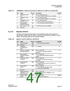
4.2.9
1000BASE-T Control
The VSC8601 device’s 1000BASE-T functionality is controlled by the bits in register 9 of
the main register space. The following table lists the settings and readouts available.
Table 17.
1000BASE-T Control, Address 9 (0x09)
Bit
Name
Access Description
Default
15:13 Transmitter
test mode
R/W
000 = Normal.
000
001 = Mode 1: Transmit waveform test.
010 = Mode 2: Transmit jitter test as master.
011 = Mode 3: Transmit jitter test as slave.
100 = Mode 4: Transmitter distortion test.
101 to 111 = Reserved: Operation not defined.
12
11
Master/slave
manual
configuration
R/W
R/W
1 = Master/slave manual configuration enabled.
0
0
Master/slave
value
This register is only valid when bit 9.12 is set to 1.
1 = Configure PHY as master during negotiation.
0 = Configure PHY as slave during negotiation.
10
9
Port type
R/W
R/W
R/W
R/W
1 = Multi-port device.
0 = Single-port device.
0
1000BASE-T
FDX capability
1 = PHY is 1000BASE-T FDX capable.
CMODE
CMODE
0x00
8
1000BASE-T
HDX capability
1 = PHY is 1000BASE-T HDX capable.
7:0
Reserved
Note Transmitter Test Mode (bits 15:13) operates in the manner described in IEEE
standard 802.3, section 40.6.1.1.2.
Revision 4.1
September 2009
Page 44

 VITESSE [ VITESSE SEMICONDUCTOR CORPORATION ]